| Issue |
Metall. Res. Technol.
Volume 116, Number 5, 2019
Inclusion cleanliness in the metallic alloys
|
|
|---|---|---|
| Article Number | 510 | |
| Number of page(s) | 8 | |
| DOI | https://doi.org/10.1051/metal/2019013 | |
| Published online | 09 August 2019 | |
Regular Article
Preparation of alumina particle suspension in liquid tin using a pre-coating process
Mines Saint-Étienne, Univ Lyon, CNRS, UMR 5307 LGF, Centre SPIN,
42023
Saint-Étienne, France
* e-mail: sylvain.martin@emse.fr
Received:
17
November
2018
Accepted:
14
March
2019
This paper presents a process and its variants to prepare alumina particle suspension in liquid tin alloy. Complication may arise due to the non-wettability of alumina by tin alloy. For this purpose, prior to introduce the powder into the liquid metal, the particles of alumina are covered by a thin layer of tin metal by using a controlled milling process. The operating conditions leading to an optimal coverage without particle damage and to a good dispersibility in the liquid metal have been searched.
Key words: liquid metal / coating / wetting / milling / alumina
© J.-M. Auger et al., published by EDP Sciences, 2019
 This is an Open Access article distributed under the terms of the Creative Commons Attribution License (http://creativecommons.org/licenses/by/4.0/), which permits unrestricted use, distribution, and reproduction in any medium, provided the original work is properly cited.
1 Introduction
The production of “clean” metal or alloy is a great challenge for steel and aluminium industry [1]. Steel-making processes include a de-oxidation step in which a reducing agent, aluminium, for instance, is added to the liquid steel. The consequence is the formation in the bath of metal oxide particles. The size range of these inclusions is wide in an industrial reactor. There are many reasons for that: inclusions nucleate and grow into the reactor due to the supersaturation; later on, the 1–10 μm alumina inclusions aggregate when the particle concentration is high enough and the particle size is large enough, as well. So, an important phenomenon undergone by the particles is the aggregation under shear: micronic particles collide within the smallest eddies of the turbulent flow corresponding to the viscous regime of turbulence. Observations show that these ramified clusters of 50 to 300 μm keep a strong cohesion in spite of the highly turbulent conditions created by the melt flow in certain parts of the reactor. These clusters are responsible for defects which may seriously alter the steel mechanical properties. Same phenomena affect the molten aluminium reactors.
The conditions of formation and the characteristics of these aggregates have given rise to several works for many years. The non-wetting of particles by the liquid metal has been identified as a property which leads to particle clusters different in size and porosity from those formed into a wetting medium [2–4]. Assumption of gas bridges between particles was put forward in this case too to explain the high cohesion and size of the observed agglomerates. By using the analogy with aggregation of hydrophobic silica particles in water-ethanol solution [5], we clearly proved that the unusual optical properties of the aggregates could be explained by the invasion of their structure by gas pockets. However, few studies have been dedicated to the aggregation of particles in a non-wetting liquid which is characteristic of metal oxides in liquid metal [6]. Some theoretical works about particles in a non-wetting liquid and their aggregation [7] have been achieved in the past. However, even less studies are concerned with its experimental aspects [8]. The reasons are related to the difficulties to perform such experiments: handling of liquid metal, use of high temperature reactor, introduction and dispersibility of particles into the liquid and finally morphological characterization of clusters in the metal [9].
The study of aggregation kinetics generally requires the use of dedicated reactor as the Couette reactor in which the shear flow is well controlled [10]. We aimed to study the aggregation of metal oxide particles in a liquid metal into a Couette reactor. The lab-scale Couette reactor has been designed in order to be representative of the aggregation of inclusions within a steelmaking ladle (particle concentration, mean particle size, shear rate). The selected particles will be micronic alumina as present in industrial metallurgical reactors. The medium will be a low-melting metal as tin or tin-bismuth alloy. The main physical parameter for characterizing the wettability of a material in a given liquid is the wetting angle. This depends on the temperature and the composition of the liquid phase. In the case of alumina in pure tin, the wetting angle is equal to 122° at high temperature T = 1373 K [11,12] and 124° at melting temperature T = 505 K [13]. The decrease of the wetting angle with the temperature is very small as expected for non-reactive metal-oxide system [11]. Thus, it is expected that liquid tin does not wet the alumina particles. D.R. Sageman [14] has performed measurements for systems with Sn and Bi: the contact angle for the liq Sn/Al2O3 system is 140° at 520 K, whereas the contact angle for the liq Bi/Al2O3 system is 123° at 560 K. We note the small deviation between the data of Sageman and Lawrence. However, the contact angles of the two systems are larger than 120°. We will assume in the following that it is also the case if the molten metal is the Sn-Bi alloy. As previously mentioned, the main challenge is to manage such suspensions, i.e. the ceramic particles have to be well dispersed into the liquid metal before the aggregation is triggered by stirring for instance.
Due to the difficulty of experiments involving liquid metals, literature on wettability in those fields concentrates either on elementary surface/interface energy measurement (mostly through sessile drop method [15,16]) or its uses in various processes. In the latter case, microscopic details are ignored in favor of efficient (and material-specific) tricks leading to the best final properties. Common examples linked to wettability enhancement include:
-
magnesium additions in aluminium melt to allow alumina, silicon carbide, or graphite particles wetting [17–20];
-
metallic pre-coating [21] or physical/chemical alteration ([22]-thermal treatment case) of particles surfaces;
-
in situ coating through chemical reaction during liquid/solid contact (called reactive wetting [26]).
In the most general case, wettability of a solid can be ensured by the addition of a layer with a similar chemical nature as the liquid phase. In the context of this article, several non-liquid phase deposition techniques for metals were tested, in order to obtain such a wettability-enhancing surface layer on oxide particles. Several methods were unable to produce any metallic coating:
-
mechanical setting of alumina particles in tin sheets (done by rolling particles between metal sheets) was impossible due to tin surface oxide hardness;
-
aluminothermic synthesis, through reaction in a SnO2, Al, Al2O3 mix, leading to partial oxidation of aluminium and reduction of tin oxide. However, chemical products were segregated, defeating the purpose of this production method.
On the other hand, various coating protocols were successful but inefficient:
-
tin sputtering (electron-beam physical vapor deposition), limited by its very low production rate and incomplete particles coating;
-
Sn2+ chemical reduction in oxide particles aqueous suspensions, using a variant of the palladium-activated protocol described in literature for tin deposition on polymers [27], which led to an unsuitable porous mix of particles, metallic tin and numerous process impurities.
In the light of these preliminary results, another approach has been investigated, taking advantage of soft metals (tin) ductility to mechanically cover hard oxide particles with a wettability-enhancing metallic layer. The aim of this study is thus to assess the potential of controlled milling process to obtain a soft metal coating, which can allow the wetting of ceramic particles by liquid metals. This will be done first by identifying the powder coating parameters and proper analysis methods needed to determine process efficiency. Processing parameters influence on the deposited metal layer will then be evaluated, and macroscale wettability experimental results will confirm the possibility to use mecano-synthesis pre-coating in the production of metal/ceramic composites.
The rest of the paper is organized as follows: Section 2 describes the materials and methods. Section 3 compares the two protocols used for enhancing the wettability of alumina by liquid tin and discusses the influence of some operating parameters on the quality of the alumina-tin suspension. Section 4 concludes the paper.
2 Materials and methods
2.1 Coating process
Coating material sources consist of high purity particulate tin, with sizes ranging from micrometric to millimetric scales. This scale dispersion allows the study of interactions between metal sources and oxide particles of varying size ratios. Tin source for coating is pure tin (99.99%), chosen for its chemical similarity with the alloy and its ductility. This metal comes in two forms: powder (drop shaped particles, with diameters ranging from 70 μm to submicrometric) and millimetric granules (Alfa Aesar 5 mm granules).
Oxide particles acting as substrates to coat are high purity alumina powders of various size distributions and shapes. These materials are amongst the most common and chemically stable oxide powders. Coating tests were carried out on two different powder types:
-
coarse alumina powder (noted c-Al2O3): α-alumina (polishing grade PRESI alumina 20 μm), showing a tabular shape with diameters comprised mostly between 5 and 20 μm (Fig. 1a);
-
fine alumina powder (noted f-Al2O3): α-alumina (Martoxid MR70 from Albemarle), with a mean diameter around 1 μm, with aggregates as large as 50 μm (Fig. 1b).
Coating experiments were carried out by means of a milling protocol. A planetary mill (PM400 from Retsch) has been used. A small alumina jar (50 mm diameter) was used as a container. The milling load consisted of 50 g of alumina balls, distributed as 2 large spheres (20 mm diameter) and smaller ones (10 mm). Powder loads were comprised between 5 and 10 g (1/5 to 1/10 ratio). A static atmosphere of pure argon was used to limit tin oxidation during the coating process.
Except noted otherwise, jar and balls were cleaned between each experiment, using the following procedure:
-
balls and jar separate rinsing with distilled water;
-
ultrasonic bath cleaning (5 minutes);
-
distilled water rinsing and tissue wiping;
-
ethanol final rinsing.
The various parameters and conditions studied are detailed below:
-
milling sequence: the milling protocols tested had one or two steps; in the first case, oxide powder and metal source were mixed and milled at the same time. The two-steps sequence consisted first in a preparation step involving the tin source alone leading to a metal layer on the jar walls, then a coating step with the introduction of oxide powder. Depending on the experiment, the metal source could be kept or removed from the jar between the steps, the former being indicated by a + symbol in the protocol description in Table 1;
-
milling speed: rotation speed varied between 150 and 400 rpm;
-
presence of milling process control agent: in order to investigate the effect of a process control agent, which is classically used for controlling plasticity during mechanical alloying, 1 wt.% of stearic acid was added to some milling batches. This additive was mixed with either the metal source alone during preparation step, or added to the oxide powder/metal source mix during coating step.
Experimental conditions investigated for powders coating are summarized in Table 1.
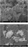 |
Fig. 1 a: coarse alumina powder (SEM image); b: fine alumina powder (SEM image). |
Summary of milling experimental conditions.
2.2 Wettability testing
The alloy used for wettability experiments after coating is the tin/bismuth eutectic (commercial name CERROTRU from Metaconcept, 43 wt.% Sn, henceforth noted Sn/Bi), its main advantage being its low melting point (412 K).
Due to the complex surface properties of liquid metals, classical wettability tests such as contact angle measurements are very dependent on experimental conditions (temperature [28,29], atmosphere [30], duration [31], contamination [17]…). Furthermore, data obtained are local and simplified (not taking surfaces roughness or shapes into account, for example), thus highlighting the need of a measuring method nearer from industrial conditions. In order to confirm wettability in liquid metals, 5%vol. of coated powders were added (over a 20 min duration) to stirred Sn/Bi alloy (300 g – 37 ml at 300 rpm/200 °C). The volume fraction value has been selected to insure the easy observation of particles by SEM (scanning electronic microscope). Melting was conducted in Pyrex glass beaker using electric sand heater, which was transferred to thermostatic oil bath for particles addition and mixing. No gas shielding was used given the protective nature of tin oxides. The resulting slurry was then cast as cylindrical ingots, which were cut and observed through SEM. The 473 K mixing temperature, comprised between eutectic (412 K) temperature and tin melting point (505 K), ensures thermodynamic stability of the coating during wetting experiments.
2.3 Characterization methods
Particle size measurements were carried out using a Malvern Mastersizer HydroS laser granulometer, with water as a dispersion medium. Testing was conducted to estimate the error in measurements induced by metallic coating. This was done by comparing size distribution of coated alumina powder before and after chemical removal of the metal layer (3 hours etching in 38 wt.% hydrochloric acid, alumina being non reactive), with no measurable difference as a result.
Jeol 6500F FEG scanning electron microscope (SEM) was used for surface observations. In the most frequent configuration, powder samples were simply deposited on carbon adhesive before introduction in SEM chamber. For further investigations, cross-sections of particles samples were prepared by polymer cold mounting followed by polishing down to 0.25 micrometers. In the cases of known insulating materials (uncoated powders and mounted samples), an additional gold layer was added by sputtering to avoid electrical charging under SEM beam.
Qualitative estimations of local composition were obtained by energy dispersive spectrometry (EDS) associated with SEM equipment. The procedure was carried out directly on a high number of coated particles using low magnification (powder sample deposited on carbon adhesive), and averaged on at least three measurements for each powder batch. This method being limited to surface analysis (1 μm depth), it overestimates greatly tin fraction (the surface layer), and was only used for comparison purposes between milling protocols.
Quantitative measurements resulted from atomic emission spectroscopy (inductively coupled plasma, ICP-AES). Samples were prepared by complete dissolution of tin surface layer in concentrated (38 wt.%) hydrochloric acid (0.2 g of coated powder for 2 mL acid), thus leading to a 0.01 wt.% precision.
3 Results and discussion
This section presents several experiments performing the partial or total coating of alumina particle by tin and the proof that coated alumina particles may be included into the liquid tin-bismuth alloy.
3.1 Effect of fine powder as coating source
No coating was obtained for experiments involving Sn powder as the source for coating material. However, f-Al2O3 milling (sample No. 1) leads to the formation of a macroscopic (millimetric) aggregates between tin and alumina through cold welding. The resulting material from these experimental conditions is highly porous; electrically-charging oxides visible in SEM reveal some level of contact between phases, but with incomplete coating. Furthermore, the presence of porosity (and thus gas bubbles) is a severe impediment to particles wettability in liquid metals. The non-wettability is due to the high reactivity of fine metal powder with oxygen. As a consequence, the millimetric granule as tin source has been used from now.
3.2 Single step milling process
Various milling durations and speed were compared through experiments No. 2 to 6. In all cases, the single step protocol allowed tin coating deposition, which was visible as a gray coloration of the powder and confirmed by EDX analysis. Darkening of the powder obtained with higher energy milling (faster speed and longer duration) demonstrated a more efficient tin transfer.
However, high speed (300 rpm) milling conditions were very damaging to the oxide powder, leading to an important reduction of mean particle diameter (from 15 to 3.5 μm – see Fig. 2), while softer processes (150 rpm) resulted in minimal fragmentation, but also in a partial coating.
Cross-sections of granules used as metal source revealed the presence of a surface layer containing aggregated alumina and tin (see Fig. 3), with thickness ranging from 20 to 60 μm.
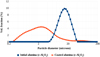 |
Fig. 2 Comparison of alumina particles size distribution before and after coating (sample No. 2). |
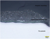 |
Fig. 3 Aggregated alumina layer on tin granule surface – the disturbed area between granule and layer created during polishing is due to hardness difference (cross-section/optical microscope ×50). |
3.3 Two steps milling process
Experiment No. 9 shows the characteristics resulting from two-steps milling process. X-ray diffraction analysis of the resulting powder (see Fig. 4) confirmed the deposition of metallic tin, tin oxides being absent or in quantities so low as to be indiscernible. EDS chemical analysis on surface of cross-sectioned alumina particles revealed only aluminium and gold (issued from the sputtered layer added to insure electrical conductivity of the samples under SEM beam).
Furthermore, the damage incurred by alumina particles was low, which was confirmed by comparing the particle size distributions of alumina before and after milling (Fig. 5). The only visible effect was a small increase in particles with diameters between 1 and 10 micrometers.
Experiments No. 7 and 8 highlight the mechanism of metal coating during milling. The preparation step led to tin deposition from granules to the jar and balls surfaces, visible as a black layer (Fig. 6a). This coating was then cleaned during the second step (Fig. 6b) and transferred to the powder which took a gray/black hue. Color comparison with the powders produced by experiments with single milling step (No. 2 to 6) reveals a larger tin deposition when multiple steps protocols are used.
In experiments No. 10 and 11, 1 wt.% of stearic acid was added separately during preparation or coating step. This additive, although commonly used to control plasticity mechanisms during mechanical alloying, forbids any transfer from tin source granules to alumina, irrespective of during which step its addition is done. No tin quantity was discernible through EDS analysis. The most probable explanation of this phenomenon is a very quick coating of alumina and tin by stearic acid during milling (due to its inferior ductility compared to tin), making direct contact between these two materials impossible without removal of the process control agent.
The effect of milling speed and duration for two-steps protocol has been also considered. Experiments No. 12 to 17 evidenced an increasing metal coating with milling duration and speed (preparation step being identical in each of these tests). Table 2 summarizes the approximate tin fraction in these samples (ICP-AES measurements), and the median diameter of coated particles. The fragmentation of particles during the milling step can be observed on the particle size distribution (Fig. 7). Thus, combining the ICP measurements, the PSD and assuming an homogeneous coverage of particles, one can determine the order of magnitude of the tin layer thickness. For example, considering experiment 12, it leads to an estimation of 0.1 µm.
The bimodal size distributions induced by fragmentation suggest that the predominant mechanism could be erosion: the size ratio between the small and large particles is about 0.05 whereas the corresponding volume ratio of these two modes is within the range 0.03–0.05 (0.2 for sample 17, which behaves differently from other samples). Erosion leads to a larger number of small particles as compared to the number of large particles. The surface area of the sample increases as erosion is running: this allows the alumina powder to be more covered with tin. However, 150 rpm/15 min coating conditions led to minimal damage to the powder, while still allowing tin deposition.
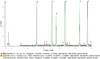 |
Fig. 4 XRD analysis of coated powder (sample No. 9). |
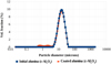 |
Fig. 5 Comparison of alumina particles size distribution before and after coating (sample No. 9). |
 |
Fig. 6 Visual evolution of milling jar and balls through a two-steps milling protocol. a: dark tin covering after preparation step; b: partially cleaned surfaces after coating step (tin transferred to alumina powder). |
Effect of milling speed and duration.
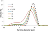 |
Fig. 7 Effect of coating step milling speed and duration on alumina particles size distribution; reference is uncoated alumina. |
3.4 Coating mechanism
Experimental comparisons between the one-step and two-steps processes with granules as tin sources allow to link coating deposition with an abrasion mechanism:
-
in the case of a one-step process, the mix of tin granules and alumina powder, together with the high ductility of tin (surface microhardness measured around 150 HV), leads to the setting of oxides particles on the granule surfaces (granules being much larger than particles). As a result, metal sources are quickly covered with a very hard and abrasion-resistant layer, which forbids further transfer from granules to powder, thus forbidding further coating deposition;
-
in the case of the two-steps process, the preparation stage, through repeated impacts with milling balls, causes work-hardening of granules surfaces. This protective layer, while not as hard as oxides (surface microhardness measured over 1000 HV), limits the insertion of particles during the second stage, while still allowing damage through friction. Abrasion of granules by the powder is then possible, accounting for the much higher amount of tin on the oxide particles. This effect seems confirmed by the low metal fraction obtained when the metal sources are removed between the two stages.
3.5 Wettability of coated alumina
Herein we compare the wettability of powders issuing from the most promising coating processes (i.e. with the highest possible tin contents), and uncoated alumina as a reference:
-
pure alumina powder could not be mixed with the alloy, simply floating on its surface without being wetted. No oxide particle could be detected in the metal. This confirms the very high interfacial energy between the alloy and alumina;
-
total wetting of sample No. 12 was attained, as attested in Figure 8 (full contact between particles and metal matrix);
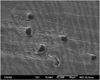
Fig. 8 SEM picture of alumina particles in Sn/Bi ingot (sample No. 12).
-
alumina powder of sample No. 9 was not visible anymore after Sn/Bi mixing, but SEM observations of the ingot revealed only partial wetting of the particles, the majority being imprisoned in gas bubbles. This incomplete wetting is the consequence of partial particles coating, due to the combination of the powder high specific surface, and lower metal transfer (two-steps protocol with tin source removed). This is further confirmed by the demixing phenomenon that can be observed if melt stirring is interrupted, in which bubbles rise to the surface and release dry powder.
4 Conclusion
Oxide powder milling with soft metal (tin) source has been confirmed as a practical and efficient process to obtain a metallic layer on particles surfaces. Parametric study of processing variables has led to the identification of necessary conditions for metal deposition: macroscopically sized tin source (granulated), and absence of process control agent.
Two different kinds of protocols have been tested, one being a single step milling of oxide powder/tin mixes, and the other a two-steps process, involving first a milling of the metal source, then a transfer stage (coating step) applied to the ceramic powder.
During the single step process, tin deposition is enhanced by higher milling speed and duration, while particles fragmentation seems mostly linked to milling speed.
Clues have led to the hypothesis that the coating mechanism is mostly linked to abrasion of hard metal surface, thus explaining the superior efficiency of the two-steps process, which include high energy milling (and thus work-hardening) of the metal source.
As a conclusion, experimental conditions for optimal tin coating can be summarized as: two-steps process; low surface to coat (coarse powder) relative to the metal source quantity; long duration, high energy (milling speed), and excess metal during the coating step. It is worth noting, however, that high speed during the second milling step leads to fragmentation of the coated powder, and is not necessary to obtain a metallic layer if initial granulometry is to be maintained. Finally, dispersion experiments have shown that, the metal layer obtained through optimal processing conditions is sufficient to ensure complete wettability of oxide powders in liquid tin/bismuth alloy. The aggregation experiments in the Couette reactor will be performed in the near future.
Acknowledgements
This research work was carried out in the context of French/German FLOTINC project (ref. ANR-15-CE08-0040), funded by ANR (Agence Nationale de la Recherche) and DFG (Deutsche Forschungsgemeinschaft).
References
- L. Zhang, B.G. Thomas, X. Wang, K. Cai, Evaluation and control of steel cleanliness – Review, 85th Steelmaking Conference Proceedings, ISS-AIME, Warrendale, PA, 2002, pp. 431–452 [Google Scholar]
- P. Kozakévitch, M. Olette, Rôle des phénomènes superficiels dans le mécanisme d’élimination des inclusions solides, Rev. Métall. 68, 635–646 (1971) [CrossRef] [Google Scholar]
- S.T. Johansen, S. Taniguchi, Prediction of agglomeration and break-up of inclusions during metal refining, in: Barry Welch (Ed.), Light metals, TMS, 1998, pp. 855–861 [Google Scholar]
- M. Cournil, F. Gruy, P. Gardin, H. Saint-Raymond, Experimental study and modeling of inclusion aggregation in turbulent flow to improve steel cleanliness, Phys. Stat. Sol. (a) 189, 159–168 (2002) [CrossRef] [Google Scholar]
- F. Gruy, M. Cournil, P. Cugniet, Influence of nonwetting on the aggregation dynamics of micronic solid particles in a turbulent medium, J. Colloid Interface Sci. 284, 548–559 (2005) [Google Scholar]
- A.R. Kennedy, The incorporation of ceramic particles in molten aluminium and the relationship to contact angle data, Mater. Sci. Eng. A 264, 122–129 (1999) [CrossRef] [Google Scholar]
- M. Cournil, F. Gruy, P. Gardin, H. Saint-Raymond, Modelling of solid particle aggregation dynamics in non-wetting liquid medium, Chem. Eng. Process. 45, 586–597 (2006) [Google Scholar]
- T. Li, S. Shimasaki, S. Taniguchi, K. Uesugi, Turbulent coagulation of solid particles in molten aluminium: kinetics of cluster formation, 13th Int. Conf. on aluminium alloys, 2012, pp. 1337–1342 [Google Scholar]
- T. Li, S. Shimasaki, S. Taniguchi, S. Narita, K. Uesugi, 3-dimensional analysis of irregular shaped particles in solid aluminum, CAMP-ISIJ 17, 985 (2012) [Google Scholar]
- V. Oles, Shear-induced aggregation and breakup of polystyrene latex particles, J. Colloid Interface Sci. 154, 351–358 (1992) [Google Scholar]
- D. Chatain, L. Coudurier, N. Eustathopoulos, Wetting and interfacial bonding in ionocovalent oxide-liquid metal systems, Rev. Phys. Appl. 23, 1055–1064 (1988) [CrossRef] [Google Scholar]
- A. Léger, L. Weber, A. Mortensen, Infiltration of tin bronze into alumina particle beds: Influence of alloy chemistry on drainage curves, J. Mater. Sci. 49, 7669–7678 (2014) [Google Scholar]
- J. Lawrence, Wetting and bonding characteristics of selected liquid metals with a high power diode laser treated alumina bioceramic, Proc. R. Soc. A 460, 1723–1735 (2004) [CrossRef] [Google Scholar]
- D.R. Sageman, Surface tension of molten metals using the sessile drop method, PhD thesis, Iowa State University, 1972 [CrossRef] [Google Scholar]
- J. Hashim, L. Looney, M.S.J. Hashmi, The wettability of SiC particles by molten aluminium alloy, J. Mater. Process. Technol. 119, 324–328 (2001) [CrossRef] [Google Scholar]
- A. Abbasalizadeh, L. Muhmood, A. Danaei, A. Barati, A. McLean, S. Seetharaman, A sessile droplet study of iron-carbon-sulfur alloys on an alumina substrate, in: Proc. Ninth Int. Conf. Molten SlagsFluxes SaltsMOLTEN12, Beijing, 2012, p. 8, Available from http://cstm.cnki.net/stmt/TitleBrowse/KnowledgeNet/ZGJS201205002065?db=STMI8515 [Google Scholar]
- G. Ramani, T.R. Ramamohan, R.M. Pillai, B.C. Pai, Stability of non-wetting dispersoid suspensions in metallic melts, Scr. Metall. Mater. 24, 1419–1424 (1990) [CrossRef] [Google Scholar]
- B.C. Pai, G. Ramani, R.M. Pillai, K.G. Satyanarayana, Role of magnesium in cast aluminium alloy matrix composites, J. Mater. Sci. 30, 1903–1911 (2016) [Google Scholar]
- B.F. Schultz, J.B. Ferguson, P.K. Rohatgi, Microstructure and hardness of Al2O3 nanoparticle reinforced Al-Mg composites fabricated by reactive wetting and stir mixing, Mater. Sci. Eng. A. 530, 87–97 (2011) [CrossRef] [Google Scholar]
- B.C. Pai, S. Ray, K.V. Prabhakar, P.K. Rohatgi, Fabrication of aluminium-alumina (magnesia) particulate composites in foundries using magnesium additions to the melts, Mater. Sci. Eng. 24, 31–44 (1976) [CrossRef] [Google Scholar]
- F.A. Badia, P.K. Rohatgi, Dispersion of graphite particles in aluminium castings through injection of the melt, Am. Foundry Soc. Trans. 76, 402–406 (1969) [Google Scholar]
- V. Agarwala, D. Dixit, Fabrication of aluminium base composite by foundry technique, Trans. Jpn. Inst. Met. 22, 521–526 (1981) [CrossRef] [Google Scholar]
- S. Tahamtan, A. Halvaee, M. Emamy, M.S. Zabihi, Fabrication of Al/A206-Al2O3 nano/micro composite by combining ball milling and stir casting technology, Mater. Des. 49, 347–359 (2013) [Google Scholar]
- B.C. Pai, P.K. Rohatgi, Production of cast aluminium-graphite particle composites using a pellet method, J. Mater. Sci. 13, 329–335 (2016) [Google Scholar]
- S. Amirkhanlou, B. Niroumand, Fabrication and characterization of Al356/SiCp semisolid composites by injecting SiCp containing composite powders, J. Mater. Process. Technol. 212, 841–847 (2012) [CrossRef] [Google Scholar]
- E. Saiz, R.M. Cannon, A.P. Tomsia, Reactive spreading in ceramic/metal systems, Oil Gas Sci. Technol. 56, 89–96 (2001) [CrossRef] [Google Scholar]
- E. Matijevic, A.M. Poskanzer, P. Zuman, The characterization of the stannous chloride/palladium chloride catalysts for electroless plating, Plat. Surf. Finish. 62, 958–965 (1975) [Google Scholar]
- E. Pastukhov, V. Chentsov, A. Kiselev, L. Bodrova, A. Dolmatov, E. Popova, S. Petrova, Wetting of graphite surface by the aluminium alloys melts, in: n.d [Google Scholar]
- P. Huber, O.G. Shpyrko, P.S. Pershan, H. Tostmann, E. DiMasi, B.M. Ocko, M. Deutsch, Wetting behavior at the free surface of a liquid gallium-bismuth alloy: An X-ray reflectivity study close to the bulk monotectic point, Colloids Surf. Physicochem. Eng. Asp. 206, 515–520 (2002) [CrossRef] [Google Scholar]
- N. Takahira, T. Yoshikawa, T. Tanaka, L. Holappa, Unusual wetting of liquid bismuth on a surface-porous copper substrate fabricated by oxidation-reduction process, Mater. Trans. 48, 3126–3131 (2007) [CrossRef] [Google Scholar]
- M. Humenik, W.D. Kingery, Metal-Ceramic Interactions: III, Surface tension and wettability of metal-ceramic systems, J. Am. Ceram. Soc. 37, 18–23 (1954) [Google Scholar]
Cite this article as: Jean-Marc Auger, Sylvain Martin, Frédéric Gruy, Preparation of alumina particle suspension in liquid tin using a pre-coating process, Metall. Res. Technol. 116, 510 (2019)
All Tables
All Figures
|
Fig. 1 a: coarse alumina powder (SEM image); b: fine alumina powder (SEM image). |
| In the text | |
|
Fig. 2 Comparison of alumina particles size distribution before and after coating (sample No. 2). |
| In the text | |
|
Fig. 3 Aggregated alumina layer on tin granule surface – the disturbed area between granule and layer created during polishing is due to hardness difference (cross-section/optical microscope ×50). |
| In the text | |
|
Fig. 4 XRD analysis of coated powder (sample No. 9). |
| In the text | |
|
Fig. 5 Comparison of alumina particles size distribution before and after coating (sample No. 9). |
| In the text | |
|
Fig. 6 Visual evolution of milling jar and balls through a two-steps milling protocol. a: dark tin covering after preparation step; b: partially cleaned surfaces after coating step (tin transferred to alumina powder). |
| In the text | |
|
Fig. 7 Effect of coating step milling speed and duration on alumina particles size distribution; reference is uncoated alumina. |
| In the text | |
|
Fig. 8 SEM picture of alumina particles in Sn/Bi ingot (sample No. 12). |
| In the text | |
Current usage metrics show cumulative count of Article Views (full-text article views including HTML views, PDF and ePub downloads, according to the available data) and Abstracts Views on Vision4Press platform.
Data correspond to usage on the plateform after 2015. The current usage metrics is available 48-96 hours after online publication and is updated daily on week days.
Initial download of the metrics may take a while.