| Issue |
Metall. Res. Technol.
Volume 122, Number 6, 2025
Special Issue on ‘Advances in Powder Technologies: Highlights from EuroPM2025’, edited by Efrain Carreño-Morelli, Elena Gordo and Lars Nyborg
|
|
|---|---|---|
| Article Number | 604 | |
| Number of page(s) | 9 | |
| DOI | https://doi.org/10.1051/metal/2025079 | |
| Published online | 16 September 2025 | |
Original Article
Assessment of microchannel architectures accuracy in stainless steel 316L/red mud composite parts fabricated by binder jetting
1
Department of Mechanical Engineering, Politecnico di Milano, Via La Masa 1, 20156 Milano (MI), Italy
2
Department of Industrial Engineering, University of Trento, Via Sommarive 9, 38123 Povo (TN), Italy
* e-mail: This email address is being protected from spambots. You need JavaScript enabled to view it.
Received:
12
May
2025
Accepted:
21
July
2025
Abstract
This study investigates the accuracy of microchannels fabricated using binder jetting. The research aims to contribute to the future development of continuous-feeding anodes for direct carbon fuel cells (DCFC) within the framework of the PRIN PNRR JETCELL project. The anodes are engineered with tailored microchannel architectures to maximize surface area to improve the electrochemical efficiency, facilitate the electrolyte flow, and prevent the fuel leakage. Stainless steel 316L and red mud composites were employed, as stainless steel provides high mechanical properties, while red mud enhances sustainability and functionality for anode applications. By systematically varying microchannel dimensions and spacings, the manufacturability and structural fidelity of micro-scale features critical to device performance have been assessed. Dimensional analysis, conducted via confocal microscopy, reveals key insights into shape retention and dimensional accuracy. To address sintering-induced shrinkage and dimensional deviation induced by printing process, scaling factors law as a function of nominal channel size have been proposed, paving the way for more predictable and precise fabrication of advanced functional components.
Key words: Microchannel architectures / binder jetting / direct carbon fuel cell / composite materials / red mud / dimensional accuracy
© N. Shang et al., Published by EDP Sciences, 2025
 This is an Open Access article distributed under the terms of the Creative Commons Attribution License (https://creativecommons.org/licenses/by/4.0/), which permits unrestricted use, distribution, and reproduction in any medium, provided the original work is properly cited.
1 Introduction
Fuel cells, which generate energy through electrochemical reactions, have aroused interests in the past few decades owing to rising concerns about clean and renewable energy. Direct carbon fuel cells (DCFC) are expected to be an alternative solution to coal-fired power generation, avoiding combustion and polluting gas emissions. The DCFC device consumes solid carbonaceous fuels at the anode and generates electricity along with pure CO2 that is available for direct capture and utilization. The fundamental half-reactions involve: at the anode C + 2O2− → CO2 + 4e−; at the cathode O2 + 4e− → 2O2−. Based on the type of electrolytes, DCFC can be subdivided into solid oxide DCFC, molten carbonate DCFC and molten hydroxide DCFC [1]. The theoretical efficiency of DCFC reaches near 100%, outperforming all other forms of fuel cell devices [2–4]. However, the replenishment of solid fuels is typically batch-fed, resulting in a less reliable and discontinuous supply compared to gases, which limits the overall system efficiency. Such limitation makes DCFC difficult to commercialize [5].
Red mud (RM) is a biohazardous waste, which is an unavoidable by-product of aluminium production. The composition of RM differs due to the Bauxite source and processing conditions, but generally it comprises greater than 30 wt.% hematite, 5.5 wt.% calcite, 3 wt.% quartz, gibbsite, 10 wt.% diaspore, etc. [6–8]. As it is highly alkaline and contains toxic heavy metals, disposal of RM in landfills causes huge ecological impacts on the surrounding area. Nonetheless, it is currently the most common way of disposing of RM, since the recycling accounts for only 3% of its total annual production [9]. Although there are some valuable metals, the economic value of metal extraction is significantly lower than the associated costs; therefore, its reuse represents an interesting area of research. Rich in metallic oxides, RM offers functional properties beyond traditional recycling. Notably, certain metallic oxides, such as periclase and hematite, can be used as catalysts of carbon gasification for DCFC [10]. Thus, integrating RM into DCFC systems has the potential to enhance the cell performance.
As a non-fusion- and powder-based approach, binder jetting (BJ) stands out in many aspects from other additive manufacturing (AM) techniques. BJ creates green parts by layer-wisely disposing binder onto the powder bed in ambient temperature. This feature largely simplifies the fabrication of composite materials. Introducing BJ into the production of the DCFC anode enables a greater flexibility in design. Indeed, BJ-printed anodes with optimized device configurations could maximize the surface area employed in the cell reactions. In addition, the production of composites allows RM to be evenly distributed in the anode, further catalysing the oxidation of carbon. However, the printing accuracy of BJ has yet to be systematically characterized, especially for the stainless steel 316L/RM composites. The new composite ensures the structural integrity and functionality that achieves higher performance of DCFC. In addition, as a sinter-based AM technology, scale factors are required to account for the volumetric shrinkage during sintering, which have not been established. While the volumetric shrinkage of stainless steel 316L during sintering is well documented [11–13], the addition of RM is expected to affect the densification behaviour, potentially leading to deviations in the shrinkage characteristics.
The literature provides insights into various aspects of fabricating microchannel structures via BJ: Miyanaji et al. [14] investigated the effect of printing speed on the printing accuracy. Dahmen et al. [15] pointed out that the small particle size of the powder complicates the difficulty of depowdering due to the low flowability. Guo et al. [16] successfully produced the micro-frames with the channel size of 700 μm and the rib of 300 μm by using the low-binder-content ink.
Continuing the study by Dall’Osto et al. [17], the PRIN PNRR JETCELL project aims to fabricate anodes using BJ to enable continuous fuel feeding in DCFC. Moreover, the microchannel structure is critical for enhancing the performance of DCFCs as it allows electrolyte passage and increases the surface area, but it also introduces considerable challenges to the production by BJ. This study focuses on exploring the dimensional accuracy of microchannels printed via BJ and the effect of printing and sintering on the origin of dimensional deviation, paving the path for the production of tea-bag-shape anodes. The results suggest the level of accuracy in microchannel fabrication without defects arising during printing and depowdering. The authors propose refined scale factors for stainless steel 316L/RM composites to accurately compensate for sintering-induced shrinkage, ensuring the precision of final geometries for the development of the anodes of DCFC.
2 Material and methods
The powder feedstock was a mixture of stainless steel 316L (Sandvik AB, Sweden) and RM. The stainless steel 316L powder exhibits a particle size distribution characterized by D10 = 4.21 μm, D50 = 9.44 μm, and D90 = 21.13 μm. Prior to being mixed, RM powder underwent a calcination process at 1000 °C for 1 h to remove possible impurities and concentrate Fe2O3 to 28.26 wt.%. Further characterizations of calcinated RM were detailed in reference [18,19]. The calcinated RM powder was screened to separate out all powders with a particle size of less than 32 μm in order to be used as BJ powder feedstocks. To ensure that the sintered samples contain a certain amount of iron oxides providing catalytic effects, 2.5 wt.% RM was mixed with stainless steel 316L by a tumbling mixer (Girafusti T0, Adler, Italy), which rotated at 80 RPM for 2 hours.
The particle sizes of biochar were between 125 μm and 500 μm. Therefore, an ideal anode matched to the size of biochar needs to be engineered with channels around 100 μm in diameter/width to allow free flow of the electrolyte while effectively preventing the leakage of biochar particles in the cell. The microchannels (shown in Fig. 1a, 1b) were initially designed and fabricated based on different mesh sizes and thicknesses with fixed spacings at 500 μm. The mesh sizes investigated in this study were 100 μm, 150 μm, 200 μm, 300 μm, 400 μm, and 500 μm. The thickness varied from 1 mm to 3 mm in steps of 0.5 mm. In addition, the printing direction has been considered as one of factors. The samples were produced on both Y-Z plane and X-Y plane.
Following the results of the initial experiment, further tests were conducted using two selected mesh sizes (200 μm and 300 μm) and different inter-channel spacing configurations (600 μm, 700 μm, 800 μm, 900 μm, 1000 μm, 1500 μm). The schematic graph of the spacing-varying sample has been illustrated in Figure 1c. The second test aimed to enhance the mechanical strength of the printed samples by increasing the spacing between microchannels. This improvement in structural integrity allowed for the application of higher air pressure during depowdering. The thickness of the samples was focused on 2 mm and 2.5 mm. The experiment not only contributed to a better understanding of the printing accuracy but also helped establishing the relationship between depowdering efficiency and green part strength. Moreover, the finer channel design aligns more closely with the targeted architecture for anode development.
The printing was performed on an Innovent+ printer (ExOne, USA) with a printhead of 30 pL. The binder used in this study is a commercially available water-based formulation, AquaFuse BA005, supplied by ExOne. The saturation level was set at 70%, while the layer thickness was 50 μm. The samples were cured in a chamber air furnace at 180 °C for 2 hours. The depowdering process was done by brushing and compressed air. Subsequently, the parts went through the debinding process in a muffle furnace LT 07/14 (Nabertherm, Germany) at 600 °C in air for 2 hours and the sintering process at 1360 °C for 2 hours in a vacuum furnace RHTC 80/450/16 (Nabertherm, Germany) with the heating rate of 200 °C/h.
The parts were characterised on the S Neox Five Axis 3D Optical profiler (Sensofar, Spain) at both green and sintered states. The results were subsequently analysed on MountainsSPIP Version 8 (Digital Surf, France). The authors used the MountainsSPIP software to obtain the cross-sectional area from the confocal microscope data and calculated the dimensions by assuming that the features have the same dimensions in the X and Y directions.
In the green state, the dimensional deviation from nominal size was calculated based on Equation (1):
 (1)
(1)
where E is the relative dimensional error in percentage; Dm is the measured dimension; Dnom is the nominal dimension in the green state.
The dimensional change during sintering was calculated by using Equation (2), while the scale factors were calculated by using equation (3):
 (2)
(2)
 (3)
(3)
where Dgreen and Dsint are the average value of the measured dimensions in the green and sintered state, respectively.
A relationship between scaling factors and channel geometries was researched to compensate the deviation from nominal geometry caused by sintering shrinkage and printing operations. A geometrical parameter was defined by the ratio between the nominal channel size and the channel depth in the green state. In this preliminary work, data was fitted by a polynomial function as expressed by Equation (4):
 (4)
(4)
where A, B, and C are the parameters derived from fitting the empirical data.
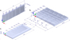 |
Fig. 1 Schematic diagram of the printed samples (unit: mm): a) Microchannel-resolution sample printed in the Y-Z plane; b) Microchannel-resolution sample printed in the X-Y plane; c) Spacing-effect sample. |
3 Results and discussion
3.1 Efficiency of depowdering
The successful and efficient removal of loose powder is a critical step in fabricating the designed microchannel structures. Observations reveal a noticeable variation in depowdering efficiency across the sample sets. Results (presented in Fig. 2) are categorized by colours: green indicates successful depowdering, yellow stands for partial depowdering, and red specifies that the feature is not depowderable. Most of the samples were successfully depowdered, except for samples with a thickness of 1 mm in the YZ print direction, which were damaged.
Channels of 500 μm and 400 μm were effectively depowdered in all cases. Depowdering of 300 μm channels was generally effective, although incomplete powder removal occurred at some thicknesses. At 200 μm, depowdering became challenging in some features. No channel less than 150 μm was completely depowdered.
Depowdering effectiveness does not exhibit a linear relationship with increasing thickness. At a thickness of 1 mm, powder removal was straightforward because the volume of trapped powder was minimal; however, the low green strength of samples at this thickness resulted in frequent failures during the depowdering process. At a thickness of 3 mm, depowdering of the microchannels features became difficult owing to the greater volume of trapped powder, the low powder flowability, and the high inter-particles friction against the channel walls, which collectively impeded depowdering. Microchannels in the XY printing direction were not depowdered as effectively as those in the YZ printing direction.
In the spacing tests, the microchannel sizes were selected at 200 μm and 300 μm with thicknesses of 2 mm and 2.5 mm. All channels could be effectively depowdered. 2 mm and 2.5 mm proved to be more reliable thicknesses in previous tests. Increased channel spacing enhanced the green strength of the printed samples and enabled the possibility of using higher air pressure during depowdering, resulting in improved depowdering effectiveness.
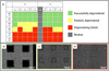 |
Fig. 2 Status of depowdering of microchannel features: a) summary chart; b) microscopy images of successfully depowdered features; c) microscopy images of partially depowdered features; d) microscopy images of unsuccessfully depowdered features. |
3.2 Microchannel size accuracy at the green state
Dimensional analysis of the fabricated microchannel at the green state was conducted to assess the initial accuracy after depowdering, which is compared to the nominal dimensions and presented in Figure 3.
For samples printed in the XY direction, dimensions were reduced by 10–25% compared to the design ones. Sample thickness had a particularly significant impact on dimensional accuracy compared to other dimensional variations observed. Samples with a thickness lower than 2 mm showed a larger dimensional error (approximately 20%), whereas those thicker than 2 mm were closer to the designed dimensions (approximately 14%). This difference was attributed to the inadequate depowdering. Since the green parts are thin and fragile, high air pressure was avoided. The increased number of printed layers enhanced the strength of the printed feature at the boundaries, thereby avoiding the mesh collapses during the depowdering process. It was also evident from the results that 400 μm and 500 μm features had similar print accuracy.
For samples printed in the YZ direction, the overall dimensional error range was 10% to 20%. This was slightly lower than that observed for samples in the XY direction, indicating that dimensions were closer to the design. Thickness still affected the dimensional error, but the trend was opposite to that observed for samples in the XY direction. Specifically, lower thickness samples were closer to the design dimensions, and the dimensional error reached its maximum at a thickness of 2.5 mm. Moreover, in contrast to samples printed in the XY direction, the size of the microchannels printed in YZ direction had an impact on the sample accuracy. It was evident that the dimensional error increases as the microchannel size decreases. From 500 μm to 300 μm, the deviation was increased approximately by 5%.
During printing in the XY direction, exceeding the capillary force with excessive binder saturation led to lateral spreading of the liquid, resulting in oversized features (i.e. the mesh struts) [20,21]. However, for features printed in the YZ direction, where the feature dimensions are determined by the cross-sectional print area of each layer and the layer thickness itself, the actual area was closer to the design value. In addition, the effect of binder bleeding was greater on single-layer samples than on multi-layer samples [22]. Larger microchannel sizes correlated with increased dimensional accuracy in green samples, which is presumed to be the results of binder bleeding.
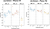 |
Fig. 3 Dimensional accuracy of microchannels of different sizes at the green state in plates with varying thicknesses: a) printed in XY plane; b) printed in YZ plane. |
3.3 Influence of microchannel size at the sintered state
Figure 4 presents the dimensions of the microchannel samples printed in XY and YZ direction after sintering. For samples printed in the XY direction (as shown in Fig. 4a), no correlation was found between microchannel sizes and sample thickness. Microchannels designed for 500 μm shrunk approximately to 350–400 μm after sintering, while 400 μm microchannels were sintered down to approximately 300 μm.
From the results presented in Figure 4b, there is a decreasing trend in dimensions as the thickness increases. For 500 μm microchannels, the size after sintering was 380 μm at a thickness of 1.5 mm, and was approximately 350 μm when the thickness increased to 3 mm. For 400 μm and 300 μm microchannels, thickness variation resulted in sintered sizes ranging from 300 μm to 275 μm and 225 μm to 190 μm, respectively. Comparing Figures 3b and 4b, the sintering process resulted in a constant deviation of the channel size showing the same trend as a function of sample thickness. Comparing the same size from Figures 4a and 4b, the final dimensions were quite overlapped, even though there was a great difference at the green state. This was attributed to the anisotropic shrinkage of the samples printed in YZ direction that is certainly different from the samples printed in the XY direction.
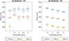 |
Fig. 4 Dimensional accuracy of microchannels of different sizes at the sintered state in plates with varying thicknesses: a) printed in XY plane; b) printed in YZ plane. |
3.4 Inter-channel spacing effects at the green state
From the previous results of the samples with the fixed inter-channel spacing, it was clear that the depowdering of the microchannel structure became difficult under 300 μm. Therefore, the new experimental objective focused on enhancing the green part strength through varied spacing between inter-channels. The depowdering effectiveness was expected to be improved by increasing air pressure. The microchannel sizes of 200 μm and 300 μm were further investigated. The thicknesses of 2 mm and 2.5 mm were specified since they ensured sufficient sample strength while avoiding difficult depowdering due to the inter-particle friction against the walls.
As the microchannel size was kept at 200 μm and 300 μm, the effect of the spacing between the channels on the printing accuracy on the green samples was shown in Figure 5.
For the microchannel size of 200 μm, the dimensional deviation is relatively significant at 600 μm inter-channel spacing (over 40%) and decreases gradually until the inter-channel spacing reaches 1000 μm, which implies that the depowdering is not very efficient. Besides, at different thicknesses, the dimensional errors also do not exhibit the same trend as the previous test, as suggested by the large standard deviations. When the inter-channel spacing exceeds 1000 μm, the results stabilized at around 30% deviation.
For the microchannel size of 300 μm, the results were more consistent, especially for samples with a thickness of 2.5 mm. A consistent dimensional error of approximately 20% was observed across all investigated spacing conditions. Samples with a thickness of 2 mm exhibited a dimensional error range between 20% and 40%. Increasing the sample thickness correlated with a stabilization of the dimensional error.
Increasing the inter-channel spacing between channels enhanced the effectiveness of powder removal due to the higher green strength and the possibility to use higher air pressure. In addition, the samples with thicknesses of 2 mm and 2.5 mm demonstrated sufficient mechanical integrity to withstand the depowdering process without sustaining damage (2.5 mm thick samples provide more consistent performance).
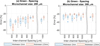 |
Fig. 5 Inter-channel spacing effects on the printing accuracy at green state with the fixed microchannel size: a) 200 μm; b) 300 μm. |
3.5 Inter-channel spacing effects at the sintered state
The dimensions of the samples after sintering are presented in Figure 6.
Sintering reduced the size of 200 μm microchannels to approximately 100 μm. This final size was independent of sample thickness, an observation consistent with previous results. Similarly, variations in inter-channel spacing did not affect the final sintered size.
From the inter-channel spacing samples of 300 μm, it was evident that the size varied from 100 μm to 180 μm after sintering. The final dimensions were strongly dependent on the size of the green samples.
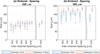 |
Fig. 6 Inter-channel spacing effects on the printing accuracy at sintered state with the fixed microchannel size: a) 200 μm; b) 300 μm. |
3.6 Scale factors of AISI316L and RM composites
As shown in Figure 7a, dimensional changes during sintering were evaluated by measuring the microchannel dimensions in both the green and sintered states. In general, shrinkage increased as the channel width-to-depth ratio decreased. This trend does not appear to be strictly related to material behaviour, but it may also be influenced by geometry and the de-powdering process. Essentially, in the green state, the microchannel size showed a significant negative deviation from the nominal size, likely due to the trapped powder. This trapped powder probably had a lower packing density compared to the powder in the inter-channel regions, leading to a low densification and, consequently, less shrinkage during sintering, explaining the observed shrinkage of less than 10%. On the other hand, shrinkage values exceeding 30% may be attributed to the measurement procedure. Slight shape distortion during sintering could lead to an underestimation of the final sintered dimensions, resulting in an apparently high shrinkage value.
The scaling factors were computed by the measured sintered dimension and the nominal green dimensions of the design models, the obtained values increased at the decrease of the channel size to depth ratio, as shown in Figure 7b. This was attributed to the increasing contribution of printing operation on the deviation from nominal geometry as described previously. Conversely, scaling factors tended to a constant value increasing the geometrical index. Essentially, the deviation originated by printing operation became negligible in comparison to sintering shrinkage at the increase of the mesh size, as generally observed in the production of conventional geometries.
Data derived from XY and YZ sampling showed similar trends, while spacing sampling significantly deviated from them. Probably the difficulty in de-powdering significantly affected the results of such samples, which were not taken into consideration for calculating scaling factor law.
Experimental data was fitted by equation (4) distinguishing XY and YZ samples. Fitting parameters and R-squared coefficient were reported in Table 1. Generally, a high correlation was found for YZ sampling, while it was less significant in XY sampling probably due to the lower number of experimental data. Notably, the C parameter determined from YZ sampling approximated the scaling factor (1.2191) derived from the average shrinkage in the Y (–16.9%) and Z (–19.05%) directions reported in [23].
Future studies will direct to enlarge the experimental observation to refine the scaling factor law. Novel geometrical index (channel size to depth ratio) can be investigated to better correlate geometry change with scaling factors. Additionally, scaling factor law will be updated including the anisotropy of dimensional change to improve the compensation of dimensional deviation occurring during sintering.
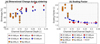 |
Fig. 7 a) channel shrinkage; b) scaling factor law as a function of the channel size to depth ratio. |
Scale factors of the AISI316L/RM composites.
4 Conclusion
Under the framework of PRIN PNRR JETCELL project, this paper explores the printing accuracy of binder jetting process in the production of microchannels. AISI316L and red mud composite was used as the powder feedstock, offering preliminary findings on the production of anode of DCFC.
This study investigated the de-powdering effectiveness and dimensional accuracy of microchannels manufactured via binder jetting process. Different samples have been produced by changing channel sizes, channel depth, inter-channel spacing, and printing direction.
Here is the list of main findings:
Microchannels in the range of 400 to 500 μm can be effectively depowdered, while channels below 150 μm cannot be completely depowdered. Channels between 200 and 300 μm can show successful, partial, or incomplete depowdering as a function of sample thickness and, consequently, of the air pressure used to avoid damaging the part.
In the green state, channels present negative deviation with respect to the nominal size, which is significantly affected by microchannel size, sample thickness, and printing direction. The deviation is attributed to binder bleeding and the possibility of having partially depowdered channels.
In the sintered state, dimensional shrinkage generally produces a significant deviation from the nominal size. Microchannel size shows a similar trend, or a flattening of the results shown in the green state.
Scaling factor laws, as a function of the channel size to channel depth ratio, are proposed for compensating the dimensional deviation originated during the printing and sintering processes. Good correlation has been found for YZ samples, while slightly lower correlation was obtained for XY samples.
In conclusion, this work experimentally investigates the achievable microchannels production using binder jetting technology and a composite material made of steel AISI316L and red mud. The influence of the printing and sintering processes has been highlighted in addition to microchannel geometry. Scale factor laws have been proposed to support the design of accurate products. This research supports the production of DCFC anodes by BJ with microchannel structures and enables the development of DCFCs towards continuous feeding.
Acknowledgments
Experimental activities were carried out in the Funtasma Lab at Politecnico di Milano and University of Trento.
Funding
This study is funded by the European Union − NextGenerationEU, under the PNRR, M4C2I1.1, JETCELL project, CUP D53D23018060001, Prot. P20225LHPX.
Conflicts of interest
The authors have nothing to disclose.
Data availability statement
This article has no associated data generated and analyzed associated with this article cannot be disclosed due to legal reason.
Author contribution statement
Conceptualization, N.S., N.L., D.M.; Methodology, N.S., M.Z. M.M.; Software, N.S., M.Z.; Writing − Original Draft Preparation, N.S., M.Z.; Writing − Review & Editing, M.M., G.D., N.L., I.C., V.F., and D.M.; Visualization, M.Z.; Supervision, N.L., D.M.; Project Administration, D.M.; Funding Acquisition, D.M. and M.Z.
References
- P. Li, Y. Han, H. Zhang, Performance assessment of a molten hydroxide direct carbon fuel cell-based hybrid system coupled with a two-stage thermoelectric generator, Int. J. Electrochem. Sci. 18, 100016 (2023) [Google Scholar]
- A.C. Rady, S. Giddey, A. Kulkarni et al., Catalytic gasification of carbon in a direct carbon fuel cell, Fuel 180, 270–277 (2016) [Google Scholar]
- D. Cao, Y. Sun, G. Wang, Direct carbon fuel cell: Fundamentals and recent developments, J Power Sources 167, 250–257 (2007) [Google Scholar]
- S. Giddey, S.P.S. Badwal, A. Kulkarni et al., A comprehensive review of direct carbon fuel cell technology, Prog. Energy Combust. Sci. 38, 360–399 (2012) [Google Scholar]
- L. Kouchachvili, P. Geddis, Q. Zhuang, Direct carbon fuel cell design for continuous operation, Int. J. Hydrogen Energy 46, 6792–6802 (2021) [Google Scholar]
- H. Gu, N. Wang, S. Liu, Characterization of Bayer red mud from Guizhou, China, Minerals Metall. Process. 29, 169–171 (2012) [Google Scholar]
- M. Zia-Ur-Rehman, H. Khalid, M. Rizwan et al., Inorganic amendments for the remediation of cadmium-contaminated soils, cadmium tolerance in plants: agronomic, Mol. Signal. Omic Approach. 113–141 (2019). https://doi.org/10.1016/B978-0-12-815794-7.00004-7 [Google Scholar]
- M.A. Khairul, J. Zanganeh, B. Moghtaderi, The composition, recycling and utilisation of Bayer red mud, Resour. Conserv. Recycl. 141, 483–498 (2019) [Google Scholar]
- E. Mukiza, L.L. Zhang, X. Liu et al., Utilization of red mud in road base and subgrade materials: a review, Resour. Conserv. Recycl. 141, 187–199 (2019) [Google Scholar]
- S. Eom, J. Cho, S. Ahn et al., Comparison of the electrochemical reaction parameter of graphite and sub-bituminous coal in a direct carbon fuel cell, Energy Fuels 30, 3502–3508 (2016) [Google Scholar]
- M. Zago, N.F.M. Lecis, M. Vedani et al., Dimensional and geometrical precision of parts produced by binder jetting process as affected by the anisotropic shrinkage on sintering, Addit. Manuf. 43, 102007 (2021) [Google Scholar]
- Z. Chen, B. Wan, J. Liu et al., Sintering densification mechanism of binder jet 3D printing 316L stainless steel parts via dimensional compensation technology, J. Mater. Res. Technol. 33, 3296–3307 (2024) [Google Scholar]
- K. Esmati, A. Chakraborty, S. Pendurti et al., Anisotropic sintering behavior of stainless steel 316L printed by binder jetting additive manufacturing, Mater Today Commun. 41, 110528 (2024) [Google Scholar]
- H. Miyanaji, N. Momenzadeh, L. Yang, Effect of printing speed on quality of printed parts in binder jetting process, Addit. Manuf. 20, 1–10 (2018) [Google Scholar]
- T. Dahmen, W.E. Alphonso, C.G. Klingaa et al., Evaluating the scalability of channels made by Binder Jetting and Laser Powder Bed Fusion using an X-ray CT and image analysis approach, in 2022 ASPE and euspen Summer Topical Meeting on Advancing Precision in Additive Manufacturing. vol. 77, American Society for Precision Engineering, Knoxville, Tennessee, United States (2022) pp. 24–29. [Google Scholar]
- H. Guo, J. Qin, S. Zhou et al., A low-binder-content ink system for 3D printing high-density and small feature size 316L stainless steel parts, Adv. Eng. Mater. 25, 2300558 (2023) [Google Scholar]
- G. Dall’osto, D. Mombelli, A. Pittalis et al., Biochar and other carbonaceous materials used in steelmaking: possibilities and synergies for power generation by direct carbon fuel cell, Biomass Bioenergy 177, 106930 (2023) [Google Scholar]
- D. Mombelli, S. Barella, A. Gruttadauria et al., Iron recovery from Bauxite Tailings Red Mud by thermal reduction with blast furnace sludge, Appl. Sci. (Switzerland) 9 (2019). https://doi.org/10.3390/APP9224902 [Google Scholar]
- D. Mombelli, C. Mapelli, C. Di Cecca et al., Riduzione di fanghi rossi d’allumina mediante fanghi d’altoforno per la produzione di ghisa, La Metall. Italiana 108, 23–41 (2017) [Google Scholar]
- F. Bertolini, M. Mariani, E. Mercadelli et al., 3D printing of potassium sodium niobate by binder jetting: Printing parameters optimisation and correlation to final porosity, J. Mater. Res. Technol. 29, 4597–4606 (2024) [Google Scholar]
- R. Jiang, L. Monteil, K. Kimes et al., Influence of powder type and binder saturation on binder jet 3D-printed and sintered Inconel 625 samples, Int. J. Adv. Manufactur. Technol. 116, 3827–3838 (2021) [Google Scholar]
- N.B. Crane, Impact of part thickness and drying conditions on saturation limits in binder jet additive manufacturing, Addit. Manuf. 33, 101127 (2020) [Google Scholar]
- M. Zago, N. Lecis, M. Mariani et al., Analysis of the causes determining dimensional and geometrical errors in 316L and 17-4PH stainless steel parts fabricated by metal binder jetting, Int. J. Adv. Manufactur. Technol. 132, 835–851 (2024) [Google Scholar]
Cite this article as: Naiqi Shang, Marco Zago, Marco Mariani, Gianluca Dall’Osto, Nora Lecis, Vigilio Fontanari, Ilaria Cristofolini, Davide Mombelli, Assessment of microchannel architectures accuracy in stainless steel 316L/Red mud composite parts fabricated by binder jetting, Metall. Res. Technol. 122, 604 (2025), https://doi.org/10.1051/metal/2025079
All Tables
All Figures
|
Fig. 1 Schematic diagram of the printed samples (unit: mm): a) Microchannel-resolution sample printed in the Y-Z plane; b) Microchannel-resolution sample printed in the X-Y plane; c) Spacing-effect sample. |
| In the text | |
|
Fig. 2 Status of depowdering of microchannel features: a) summary chart; b) microscopy images of successfully depowdered features; c) microscopy images of partially depowdered features; d) microscopy images of unsuccessfully depowdered features. |
| In the text | |
|
Fig. 3 Dimensional accuracy of microchannels of different sizes at the green state in plates with varying thicknesses: a) printed in XY plane; b) printed in YZ plane. |
| In the text | |
|
Fig. 4 Dimensional accuracy of microchannels of different sizes at the sintered state in plates with varying thicknesses: a) printed in XY plane; b) printed in YZ plane. |
| In the text | |
|
Fig. 5 Inter-channel spacing effects on the printing accuracy at green state with the fixed microchannel size: a) 200 μm; b) 300 μm. |
| In the text | |
|
Fig. 6 Inter-channel spacing effects on the printing accuracy at sintered state with the fixed microchannel size: a) 200 μm; b) 300 μm. |
| In the text | |
|
Fig. 7 a) channel shrinkage; b) scaling factor law as a function of the channel size to depth ratio. |
| In the text | |
Current usage metrics show cumulative count of Article Views (full-text article views including HTML views, PDF and ePub downloads, according to the available data) and Abstracts Views on Vision4Press platform.
Data correspond to usage on the plateform after 2015. The current usage metrics is available 48-96 hours after online publication and is updated daily on week days.
Initial download of the metrics may take a while.