| Issue |
Metall. Res. Technol.
Volume 122, Number 6, 2025
Special Issue on ‘Advances in Powder Technologies: Highlights from EuroPM2025’, edited by Efrain Carreño-Morelli, Elena Gordo and Lars Nyborg
|
|
|---|---|---|
| Article Number | 608 | |
| Number of page(s) | 14 | |
| DOI | https://doi.org/10.1051/metal/2025080 | |
| Published online | 01 October 2025 | |
Original Article
Kirkendall pore formation within WC-Co tool inserts during the machining of titanium alloys
1
Sandvik Coromant R&D, Lerkrogsvägen 19, Stockholm 126 80, Sweden
2
Division of Production and Materials Engineering, Lund University, LTH, Ole Römers Väg 1, Lund 221 00, Sweden
3
School of Chemical, Materials & Biological Engineering, The University of Sheffield, Mappin Street, Sheffield S1 3JD, UK
* e-mail: This email address is being protected from spambots. You need JavaScript enabled to view it.
Received:
12
May
2025
Accepted:
21
July
2025
Abstract
Recent research has indicated that machining of titanium alloys with uncoated cemented tungsten carbide tools fulfil the criteria for Kirkendall porosity. If this occurs during machining, it could contribute to the type and rate of tool wear, compromising the tools structural integrity close to the edge line within the contact zone. In this study, voids were observed at the tool-workpiece contact zone close to the cutting edge of worn milling inserts, generated due to the 10 000 times higher outward diffusion of Co into Ti than Ti into Co. To investigate the nature of the Kirkendall diffusion process, diffusion couples between titanium alloys and WC-6Co at pressures between 0 to 2.5 GPa and temperatures between 800 and 1200 °C were made and analysed. Porosity was found in the 1200 °C Ti-6Al-4V/WC-6Co 2.5 GPa and 1000 °C Ti-5Al-5Mo-5V-3Cr/WC-6Co 35 MPa samples in addition to the inserts. These findings highlight the need for further research into porosity-driven wear mechanisms to improve the cemented carbide tools for machining titanium alloys.
Key words: WC-Co / porosity / titanium / machining / diffusion / wear
© A. Graves et al., Published by EDP Sciences, 2025
 This is an Open Access article distributed under the terms of the Creative Commons Attribution License (https://creativecommons.org/licenses/by/4.0/), which permits unrestricted use, distribution, and reproduction in any medium, provided the original work is properly cited.
1 Introduction
The primary tool material used to machine titanium alloys is WC-Co. The machining of titanium alloys using such materials presents many challenges due to titanium’s high chemical reactivity, low thermal conductivity and low elastic modulus, all of which contribute to rapid tool wear and high machining costs. Characteristics of the wear have been well documented and include smearing/welding of titanium to the tool, leading to chipping and breakage of the edge-line [1–3]. High temperatures leading to plastic deformation of the cutting edge [4]. Spring back of the chip material resulting in cyclic loading and mechanical fatigue of already compromised tool material [1,5,6]. The most critical contributor to the wear of WC-Co cutting tools is the reactivity of the titanium with the tool material, which critically compromises the tool integrity, providing the conditions for the previously mentioned wear types to manifest [7–9].
There has been a significant body of work directed toward understanding the mechanisms by which tool integrity is compromised by the reaction of titanium workpieces with WC-Co during machining. Key factors include the rapid outward diffusion of Co from the tool into the titanium alloy [10], the loss of C from the WC leaving brittle bcc-W phase, the formation of abrasive metallic carbides MxC(1-x), where M = Ti, W, V (here after referred to as TiC), at the tool-workpiece interface.
It is of upmost importance to tool manufacturers that the mechanisms by which such factors compromise to tool material is better understood to enable the next generation of tools to be developed. This article facilitates this in two ways; (1) by providing a comprehensive review of the published literature that have contributed to the current understanding of the mechanisms driving tool wear and degradation of WC-Co tools during the milling and turning of titanium alloys. (2) Following this, by reporting and discussing, within the context of the work included within the literature review and results found by Botermans [11], thus contributing to the understanding of how rapid outward diffusion of Co from the tool during machining can significantly compromise the tool material. The work consists of an investigation of worn milling inserts in combination with diffusion couple experiments. A combination of SEM and X-EDS was then used to characterise cross sectioned inserts and diffusion couples. The results are then discussed in the context of the prior literature, specifically focusing on the formation of porosity within the tool substrate during machining with the goal to give a comprehensive overview of the critical wear mechanism, and how the tool integrity is compromised, when machining Ti alloys using WC-Co tools.
2 Literature review
In 1982, Hartung et al. [12] laid the theoretical foundations required to understand the wear mechanisms involved in titanium machining through a combination of experimental investigations and theoretical analysis. Their experimental methods included turning Ti-6Al-4V (Ti-64), by far the most utilized titanium alloy, using coated and uncoated WC-Co, polycrystalline cubic boron nitride (PCBN), and polycrystalline diamond (PCD) tooling inserts. During machining trials, thermocouples were employed, giving a rudimentary understanding of the thermal conditions close to the cutting zone. They estimated the temperature at the cutting zone was approximately 1000 °C. Using theoretical modelling and characterization techniques, including scanning electron microscopy (SEM), energy dispersive X-ray spectroscopy (X-EDS), and Auger electron spectroscopy (AES), they identified that crater wear was the tool life-limiting wear type and that it is governed by chemical reaction and diffusion between the tool material and titanium workpiece. Hartung et al. proved there was formation of a TiC layer for diamond tools but didn’t give such evidence for Cemented carbide. They postulated that TiC layer formation is key in controlling the wear rate, since such a layer would significantly retard the chemical and diffusional wear responsible for the crater. This hypothesis was supported by work in 1988 by Min et al. [10], who evidence that there was Co and C diffusion from the tool into the Ti at the Ti/workpiece interface resulting in a C rich layer, and C depletion and thus embrittlement of the tool material.
For some time, the hypothesis posited by Hartung et al. remained the leading theory on how titanium machining wear rate was mediated for both PCD and cemented carbide tools. However, unpublished work by Norgren on Ti milling [13] revealed a lack of Cobalt at the insert/adhered material interface, and that Co had diffused out into the Ti, in addition to white spots in the remaining binder at the interface, see supplementary material. It was hypothesised that the white spots W-rich were either Co3W or W, as the carbon diffusion in fcc-Co is several orders of magnitude higher than W in fcc and that the binder would thus be supersaturated with W. As indicated by the phase diagram given in Figure 1 [13], either of these phases precipitate depending on temperature, supersaturation and ease of nucleation. Also, pores were seen in the tool close to the workpiece/tool interface- resembling Kirkendall porosity. Exerts from the unpublished work, that demonstrate this, are given within the supplementary material.
Between 2016-2024 there were several works that significantly contributed to the understanding of the critical wear mechanism involved in titanium machining. The following details the key findings of said research.
Hatt et al. [14–16] highlighted how the chemical composition, and thus α (hcp-Ti) + β (bcc-Ti) content, of the specific titanium alloys significantly influences the interaction between the tool and Ti alloy workpiece. In their work, they utilized diffusion couples to analyse interfaces made between WC-Co tools and several different titanium alloys which had varying levels of α and β stabilizing elements. Alloys with increased volume fraction of β stabilizing elements, like Mo, were found to form a thinner TiC layer at the tool-alloy interface. Turning trials showed that the tool wear rate, specifically crater wear rate, was significantly faster when machining more β-rich titanium alloys. Work utilizing diffusion couples by Ramirez et al. [17], enabled further insight into the interfacial reactions and the diffusion mechanisms acting between the two material systems. SEM, X-EDS, and electron microprobe analysis (EPMA) were used to identify that there exist distinct diffusion zones. In the first affected zone, close to the bulk of the WC-Co, there was evidence that the fraction of WC was decreasing, indicating WC dissolution. Closer to the interface, in the second affected zone, a Co-rich phase was characterized, which differed from observations of Hatt et al. [15], who observed the formation of so-called η, (M6C and M12C), phases in this region. Then, in the third affected zone, at the interface itself, a TiC layer was observed. Although not discussed, in both the work by Hatt and Ramirez, Co was diffusing very rapidly into the titanium alloy [14–17], visible in their elemental images.
Odelros et al. [18] used a combined approach, including dynamic machining, static diffusion couples, and FEM and diffusion simulations to understand the crater wear mechanism. Utilizing CALPHAD-based diffusion modelling they simulated the C depletion of WC and the formation of η phase and metallic carbides due to chemical interaction, when the WC-Co/Ti-alloy system (all primary elements) was simulated. To mimic machining, the simulation was done in two parts: one between a WC grain and Ti. This showed W at the interface, also evidenced experimentally by XRD. A second simulation between the binder and the Ti showed rapid out diffusion of Co into the Ti. Such modelling supports findings using a theoretical basis, enabling a description of the mechanism to be built on fundamental foundations. SEM, X-EDS, EPMA, and X-Ray diffraction (XRD), showed that a key characteristic of the interface is the formation of “fringe-like” bcc-W, and that this phase forms in a large area within the crater. This bcc-W morphology will also be referenced in several other papers, often with different names such as “lamellar like” or “lamellae” structure, they all refer to the same morphology which can be seen in SEM as a layer made of many high contrast micron size bcc-W lamellae. Odelros et al. also showed that metallic carbides like TiC formed discontinuously at the interface within the crater. It was proposed that the dynamic flow of the chip constantly removes the TiC layer, suggesting that no consistent protective layer exists to mediate the diffusion, and instead it is more transient in nature. An important consideration is that under such conditions, diffusion couples can only provide part of the picture, and the findings from them must be considered carefully. Kaplan et al [19] independently verified the presence of bcc-W as a chemical wear product at the tool/workpiece interface using XRD. Additionally, diffraction peaks corresponding to cubic (Ti,V)C were occasionally observed and verified by EDS mapping, indicating the formation of the carbides from the reaction of released carbon with titanium and vanadium.
The key findings of Odelros et al. [18] and Kaplan et al. [19], were further corroborated and evidenced by von Fieandt et al. [20], who carried out diffusion simulations and EBSD analysis to confirm the formation of bcc-W because of carbon loss from WC due to TiC formation, and the progressive diffusion of W into bcc-Ti.
In a dynamic situation, such as that which occurs during machining it is important to identify the key mechanisms mediating the diffusion interaction if it is to be understood. To do this, detailed characterization of inserts used for machining is required. Lattemann et al. [21] studied the interaction between Ti-64 and the tool material in cryogenic machining conditions by characterizing the crater region using a combination of SEM, scanning transmission electron microscopy (STEM), STEM-EDS, and STEM-electron energy loss spectroscopy (EELS). They observed the characteristic diffusion of Co towards and into the workpiece. This occurred extremely rapidly and is a critical step in the wear mechanism. They also saw some evidence that the Ti diffused into the Co binder. In the work by Lattemann et al. [21] and Kaplan et al. [19], titanium carbides were observed to form within binder pockets, Latteman et al. showed this in TEM cross-section and Kaplan et al. in SEM top view images of the crater that forms on the tool as it wears. Both studies corroborated the findings of Odelros et al. [18], by identifying that a layer of C-depleted WC, i.e., bcc-W, forms, exhibiting a lamellar-like structure with low mechanical strength. One key distinction that Lattemann et al. were able to make, due to their high-resolution STEM-EDS/EELS, was that within the binder pockets there was also precipitates of W, as the binder was depleted of C, explaining the white spots observed by Norgren [13] although their explanation was different. They reason that the mechanically weak bcc-W lamellar has “broken off” during the chip flow, which explains how the crater becomes larger over time. Norgren on the other hand, reasons that the binder is supersaturated by W and Co3W or W precipitates form. Fragments of bcc-W were also reported by Saketi et al. [22], who observed W fragments in the chip material after machining Ti-64.
Graves et al. [23] investigated crater wear caused by machining a high strength metastable β titanium alloy Ti-5Al-5Mo-5V-3Cr (Ti-5553) used in Boeing 787 landing gears. They also used advanced characterization techniques including SEM, wavelength dispersive spectroscopy (WDS), and crucially STEM/TEM combined with EELS. The results indicated that the work by Odelros et al. [18] SEM, and simulations and by Kaplan et al. and Lattemann et al. [19,21] hit on a key characteristic of the wear mechanism when they also brought attention to the interaction occurring within the binder pockets, between the Co-binder and the Ti-alloys. The interaction between the Ti-5553 workpiece and tool material was shown to be significantly different from that occurring at the interface between solid WC grains and Ti-5553. The interaction at the interface between WC grains and the Ti-5553 workpiece, away from Co binder pockets, resulted in larger lamellar fringes of bcc-W on the surface of the WC grains that were in contact with the workpiece. The explanation put forward for this was that the higher stability of TiC versus WC and rapid diffusion of C in Ti results in decarburization of the WC at first, results in a bcc-W layer, and then that the immiscibility of W within Ti results in the bcc-W at the interface. This, in turn, results in a diffusion barrier to C due to the low solubility of C in bcc-W. In addition, the miscibility gap between Ti and W retards further solution of W into Ti and vice versa. The process occurring within prior Co-rich locations, i.e., prior Co binder pockets, resulted in TiC formation and a much finer bcc-W lamellar forming with a so-called “porous-like morphology” than the lamellar forming at the WC-workpiece interfaces. Graves et al. [23] state that decarburization and degradation of tool material are more rapid in prior Co-rich locations because: (1) more tool material had been removed in and around prior Co-rich regions and (2) C diffusion could be higher in such locations since Co can act as a diffusion matrix in the tool for C and as a β stabilizing element towards the titanium, increasing the amount of bcc-Ti in the region closest to the interface which is important since C and Co diffusion in bcc-Ti is faster than in hcp-Ti. Supporting thermodynamic simulation suggested that a liquid phase could form at temperatures above 975 °C in regions where more Co was present, through which the rate of C diffusion would further be accelerated. In addition, the porous morphology observed within Co regions was suggested to be caused by Kirkendall effects due to that the permeability (solubility*diffusion rate) of Co into Ti, which is orders of magnitude much higher than that of Ti into Co. At 1000 °C the diffusion constant for Ti into Co is ∼ 10−15 m2/s and for Co into β Ti is ∼ 10−11 m2/s which means that Co diffuses into Ti is 10 000 times faster than Ti into Co, this is shown in the supplementary material and discussed in [11]. The Co flux out into the Ti are at the same order of magnitude as C. Such porosity would inevitably compromise the integrity of the tool material in such locations. Graves et al. [23] concluded that the interaction between tool constituents and workpiece within prior Co-rich regions was critical to governing the wear rate in turning. They attributed this to the fact that accelerated decarburization in prior Co-rich locations caused a higher rate of WC breakdown, increased formation of abrasive TiC particles in the vicinity, and an accelerated reduction in the integrity of the tool.
Lindvall et al. [24] investigated high-speed turning of Ti-6Al-4V at 150, 200 and 250 m/min cutting speeds with high pressure coolant. Such speeds cause extremely high thermomechanical loads on the tool, and therefore in regions where the coolant is not present (flank and rake contact), diffusive wear mechanisms will be exacerbated. The results identified the formation of a bcc-W rich layer and titanium carbides forming due to carbon diffusion. Selected area electron diffraction (SAED) enabled identification of the specific reaction products which formed during machining including intermetallic TiCo2 and Co3W within Co binder pockets on the flank face of the tool which had been in contact with the workpiece. It is possible that such reaction products may be playing some role in mediating the diffusion within the binder pockets.
The findings of Graves et al. [23], and Lindvall et al. [24], were further corroborated by Olander et al. [25] who found that carbon depletion and W enrichment caused the formation of a so-called nano-rough surface, W rich surface with indications of TiC being present. This was caused by the fact that Co binder was removed extremely rapidly from the tool surface leaving empty pits on the tool material where it pre-existed. The work by Olander et al., further makes clear the importance of how increasing cutting parameters like the feed, speed and machined length dramatically influence the crater wear rate. Increasing cutting feed and more relevantly, speed can drastically increase the temperature at the tool chip interface and since the mechanism under review is chemical and diffusion driven many of the prior discussed research has assumed that the temperature governs the wear rate. This was supported with evidence, when Bejjani et al. [26] investigated the wear mechanism whilst controlling the temperature close to the cutting edge using cryogenic coolant. A relation between temperature and the amount of diffusion wear was established by varying the amount of cooling by varying the nozzle size used for coolant application. A 2D FEM model was used to simulate the maximum temperature at the cutting interface, indicating it to be around 978 °C, close what Hartung et al., discussed and around which much of the theoretical work done in the area is based upon.
A follow up article to [23] by Graves et al. [8] complimented the analysis of worn tools used to machine Ti-5553 with both diffusion couple experiments and detailed diffusion simulations of the process. Graves et al. [8] examined what the key differences between the static (diffusion couple) and dynamic (machining) processes were and used the findings to further elucidate the dynamic wear mechanism. This was done by simulating, using diffusion modelling, the static (closed system) and the dynamic (open system). The closed system simulation was initialized with a sharp compositional step, where the left side of the domain represented the tool material, WC-6Co, and the right side represented the workpiece material, Ti-5Al-5Mo-5V, effectively modelling a static diffusion couple. Boundary conditions were defined such that the activities of W, C, and Co were fixed on the WC-6Co side, while the activities of Al, C, Co, Ti, and V were fixed on the Ti-5Al-5Mo-5V side. The boundary diffusivities were selected to reflect the interaction between tungsten carbide and the titanium alloy. Importantly, the total carbon content in the system was held constant, implying that the activity of carbon would decrease as the system approached equilibrium. The open system simulation was initialized with a uniform composition across the entire domain, set to WC-6Co, representing the tool material. The interaction with a Ti-5Al-5V-5Mo workpiece was modelled by applying activity boundary conditions. A defining feature of this setup was that the C activity remained approximately fixed or sustained at a higher level over extended periods. This behaviour reflected the dynamic nature of machining, where fresh workpiece material was continuously introduced at the tool–chip interface, and carbon was steadily removed from the system as the chip flowed away. This ongoing removal prevented the carbon content in the chip or adhesive layer from exceeding its solubility limit. One result of conducting this work was to highlight that the permeabilities of C and Co in Ti are of the same order of magnitude (high in both cases). The simulations also highlighted that C activity plays a crucial role in determining what phases form at the tool-workpiece interface. In a closed system, as the C activity reduces as a continuous TiC layer forms and equilibrium is approached, M6C and M12C η-phase formation occurs. In contrast, when the C activity in the tool and Ti activity in the workpiece remains high and Co-content reduces, such η phases are only shown to form in trace amounts. This was shown by comparing the evidence of η phase in the diffusion couples with the lack of such phases within the crater region of worn tools. A key aspect regarding the conditions required for bcc-W formation in that when C activity is fully maximised, in a fully “open” system then bcc-W cannot precipitate. The presence of bcc-W in the crater is a result of the system being someway between open and closed, since although new workpiece material is constantly being provided, the C activity is still mediated somewhat by the formation of reaction layers which remain for short amounts of time before being removed. The fact that less bcc-W forms in the Co binder pockets than at the WC-workpiece interfaces is explained by simulation; since when there is fixed C content and varied Co mass fraction, the C activity increases with the amount of Co. Further into the tool and where Co remains it can act as a diffusion pathway for C, this is even the case for Co-monolayers that can lay between WC grains [27]. Graves et al. [8] utilised electron diffraction patterning (EDP) to show evidence of C depletion of W in the form of bcc-W, 4 μm below the crater surface, in the worn tools. The formation of such brittle phase within the substrate microstructure would indicate a compromised tool integrity. Further, these simulations also showed that at 1000 °C the solubility of Co in Ti is high and that there will be anomalously fast diffusion of Co into the Ti-5553 workpiece. In the study, this is used to explain that dark regions observed within the Co binder for the diffusion couples could be indicative of Kirkendall porosity, for which the criteria is that the diffusion flux of one element, here Co, out into Ti, is much more rapid than Ti into Co. In the article Ti, Al, V, Co, C and W was included in the simulation and of the substitutional diffusion elements only the Co flux out into the titanium was much more rapid than the flux of Ti, Al, V or W into the Co. Thus, the loss of Co into the titanium which occurs at a faster rate than the substitutional element into Co creates the conditions that satisfy the formation of Kirkendall porosity, i.e. the formation of vacancies within the Co that become voids as the process proceeds. In the case of machining, where new material is consistently replenished the conditions for Kirkendall porosity will remain. In a diffusion couple, interface layers can form, and if they hinder the diffusion of Co out into the Ti, this will retard or stop the process, and less or no porosity will occur. The formation of such porosity could be considerably detrimental to the integrity of the tool material and could contribute significantly to the rate of tool material degradation.
Lindvall et al. [9] published a comprehensive tool wear study of WC-Co tools used to do milling of Ti-6242 (near-α type), Ti-6246 (α+β type), and Ti-5553 (near-β type). Although, the maximum temperatures occurring when milling are known to be lower when compared to turning, the research showed clear evidence of the outward diffusion of C and Co from the tool into the Ti workpieces. This led to the WC grains being rounder and the formation of a bcc-W layer showing that the tool degradation mechanisms of WC-Co tools in milling titanium are like those occurring during turning. The presence of CoWO4 was observed and verified using EBSD, indicating the oxidation of the binder phase at the tool Ti alloy workpiece interface. Thermodynamic modelling supported such oxide formation. The worn inserts, used for milling, had significant crack networks propagating through the substrate. There was evidence of Ti within the cracks indicating its diffusion into the substrate. There was also CoWO4 formation within the vicinity of said cracks. The study showed that the diffusional loss of Co binder weakens the bonding between the WC grains. Then, cracks parallel to the tool surface are formed due to the mechanical cycling that occurs during milling. The observed oxidation and formation of the ceramic phase CoWO4 within the binder likely contributed to crack initiation and propagation, as this phase is brittle, fracture-prone, and can serve as a nucleation site for cracks. Additionally, as demonstrated by Graves et al. [8], carbon depletion from deeper regions within the tool substrate may lead to the formation of brittle bcc-W between WC grains. This phase potentially promotes crack development and compromises the structural integrity of the substrate, further facilitating crack propagation. Another factor which could promote and exacerbate crack formation and initiation is the presence of porosity. Porosity was evidenced within prior Co rich regions and attributed it to either, or a combination of, Kirkendall porosity (due to the Co diffusing out of the tool faster than Ti can diffuse in), or plastic deformation induced pores due to the cyclic loading which could cause voids to coalesce into larger voids within the binder.
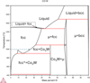 |
Fig. 1 Binary Co-W phase diagram calculated using the Thermocalc software and the binary database (TCBIN). The dashed arrow indicates the W supersaturation at a 1000 °C in the Cobalt to precipitate the Co3W phase and where fcc* denotes the magnetic fcc [13]. |
3 Material and methods
For the diffusion couple experiments two Ti alloys were investigated, Ti-64 and Ti-5553. The Ti alloys were combined with a WC substrate, grade H13A. This substrate has 6 wt.% Co and a WC grain size ∼1 μm and hardness 1600 Hv. The Ti-5553/H13A diffusion couples were fabricated at three different pressures: ∼0 MPa, 35 MPa and 850 MPa. For the Ti-64/H13A diffusion couples, the pressures used were: ∼0 MPa, 850 MPa and 2.5 GPa differed to others and is explained in this section. The temperature, ramp rate, dwell and cooling rates for the different diffusion couples are given in Table 1. Details about how each diffusion couple was manufactured can be found in [11].
3.1 Ti-5553/H13A and Ti-64/H13A ∼0 pressure
For the Ti-5553/H13A and Ti-64/H13A made at ∼0 pressure cylindrical rods 5.17 mm in diameter were sectioned from the alloy’s material using wire-EDM. The H13A inserts were sectioned into narrow 5 mm bands using a Struers Secotom-50 and diamond blade. Two faces of the titanium alloys and tool material were polished with 500 then 1200 silicon carbide grit paper to ensure the sides were flat. These were then combined into a diffusion couple by placing the either side of the sectioned tools around the titanium band. It should be noted that in this setup the pieces were stacked vertically, thus there was a minimal pressure due to this, however no external pressure was applied during the sample creation. Once the stacks were made, the diffusion couples were annealed in a FCT DEK50 sintering furnace at vacuum pressure and a heating rate of 25 °C/min. The diffusion couples were held for 120 minutes at temperatures of 800, 1000 ad 1200 °C, see Figure 2. The cooling rate after dwell was 21 °C/min until 80 °C. Since the titanium and cemented carbide are free to expand during heating it is assumed there was no pressure at the diffusion interface.
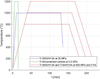 |
Fig. 2 Temperature during diffusion couple manufacture for Ti-5553/H13A and Ti-64/H13A ∼0 MPa, Ti-5553/H13A 35 MPa, Ti 5553/H13A and Ti-64/H13A 450 MPa and Ti-64/H13A 2.5 GPa. |
3.2 Ti-5553/H13A 35 MPa
This diffusion couple was made by grinding away 500 μm away from the flank of the tool using a 6 μm neoprene surface with diamond suspension. Then the insert was placed in a graphite mould of diameter 20 mm containing 20 g of Ti-5553 powder (particle size 45–150 μm). This was then placed in a sintering furnace and sintered via field assisted sintering technology (FAST) with a FCT system Hp D 25 SPS furnace. During sintering there was a constant 35 MPa pressure applied. The heating rate was 100 °C/min with a dwell time of 120 min at 1000 °C. The cooling from 1000 °C to 400 °C was at a rate of 100 °C/min, see Figure 2. The sample was then sectioned in half through the insert hole.
3.3 Ti-5553/H13A and Ti-64/H13A 850 MPa
Ti-64 and Ti-5553 cylindrical rods were sectioned using wire-EDM. Then the outside of the diffusion couples were ground using 1200 grit paper. The rods were then placed in the central clamping hole (diameter 5.156 mm) of CNMG 12 04 08-SM inserts. The rods were then cut to roughly 5 mm which was slightly above the 4.762 mm height of the insert. The rods were then compressed in a vice, resulting in radial plastic deformation, causing the diameter became the same as the insert hole and that there was good contact between the titanium alloys and the hole wall. The samples were then annealed in a FCT DEK50 sintering furnace under vacuum. The heating rate was 25 °C/min. The diffusion couples were treated for 120 min at temperatures of 800, 1000 and 1200 °C. The cooling rate was 21 °C/min until 80 °C, see Figure 2. The pressure at the diffusion interface is calculated to be 850 MPa (at 1000 °C) due to the higher thermal expansion of titanium when compared to cemented carbide. Since the pressure is estimated not to vary significantly for the temperature range used all samples are made at 850 MPa.
3.4 Ti-64/H13A 2.5 GPa
The Ti-64 2.5 GPa diffusion couple was designed using Ti-64 material with H13A ISO RNGN060300 inserts. These cylindrical inserts were placed in a HPAT–30 toroid-type high-pressure furnace and subjected to 2.5 GPa. The heating rate was 250 °C/min with a holding time of 1200 for 10 min. After this time the samples were water quenched. Wire-EDM was employed to section them parallel to the diameter of the insert.
3.5 Milling test
In the milling experiment, a Sandvik Coromant tool insert of R390-11T308M-MM geometry was used to mill the largest face of a 600 mm × 200 mm × 50 mm rectangular Ti-64 workpiece. The material was in an annealed condition, with the heat treatment temperature being controlled to 779–781 °C followed by a 3 h air cooling. The Co and Cr binder content in the carbide of the inserts used was 13.5 wt.% and 0.52 wt.% respectively, WC-13.5Co-0.52Cr. The grain size of the carbide was 0.7 μm, the hardness is 1375 Hv. The machining parameters used were: Cutting speed (vc) = 45 m/min, cutting feed (fz) = 0.14 mm, depth of cut (ap) = 2 mm, engagement (ae) = 10 mm, cutter diameter (Dc) = 32 mm, coolant pressure = 10 bar, time-in-cut = 28 min.
3.6 Mounting
The diffusion couples and the worn inserts were all sectioned and mounted in conductive Bakelite. The samples were consolidated in a Struers Citopress-15 and Buehler Simplimet 2000 equipment. A Tegramin 30 was then used to polish samples to mirror finish. Two polishing techniques were used for the samples. The method used for the Ti-5553/H13A 35 MPa samples was to grind with P400 and P2500 grit paper followed by polishing with 6 μm and 3 μm diamond suspension on a neoprene surface. The method used for all samples was to use a Stuers MD-Piano 220, Plan, Nap and Chem surface with water (30 s), DiaPro All Lar. 9 μm + water (120 s), DiaDuo-2 1 μm + water (240 s), OP-U Non-dry + water (300–600 s).
4 Results and discussion
In this paper SEM and X-EDS results for the four most relevant and indicative diffusion couples are given. These are the 1000 °C Ti-64/H13A ∼ 0 MPa, 1000 °C Ti-5553/H13A 35 MPa, 1200 °C Ti-64/H13A 850 MPa and the 1200 °C Ti-64/H13A 2.5 GPa. A summary of all the diffusion couples that were made as part of Botermans study [11] and what the notable outcomes were is given in Table 1. The characterisation results from the diffusion couples that have not been included in this paper can also be found in [11].
As can be seen from Table 1 most of the diffusion couples made at ∼0 MPa failed to form a diffusion bond. This highlights the unreliability of this method of making diffusion couples. For the ∼0 MPa diffusion couple made at 1000 °C which was the most successful at this extremely low contact pressure, in a region where there was successful bonding, SEM and X-EDS was conducted. The results of this are given in Figure 3 which shows the WC-Co substrate on top of the Ti-64 material. In the SE-SEM image, there are voids (<0.1 µm) directly at the interface. From the X-EDS, it is apparent these voids are in a Co-rich layer that has formed at the interface. It is also clear that WC or possibly bcc-W is in outward diffusion from the tool substrate, in some places this was observed to occur up to 25 μm into the Ti-64. Unlike the diffusion couples made by Hatt et al. [15] and Ramirez et al. [17], no consistent TiC layer formed in the ∼0 MPa diffusion couple, instead there is evidence of a layer of Co at the reaction interface.
A BSE-SEM micrograph and X-EDS maps for the 1000 °C Ti-5553/H13A 35 MPa diffusion couple are given in Figure 4. In the BSE-SEM image several regions are marked. Region 1 shows bulk WC grains within the Co binder as would be expected to see in a as made insert. In region 2 the binder regions are brighter in contrast, indicating higher W content, and according to the X-EDS contain slightly less Co than in region 1 indicating the presence of M6C or M12C η phase which has been predicted to form under such conditions by Graves and Salmasi et al. [8]. Within this η phase located in region 2 there is clear evidence of cavities. Although η phases have been identified and discussed by in prior research, the presence of voids within the phase is a novel finding to this work. It is plausible that such porosity has formed from either a Kirkendall effect or transformation porosity due to the volumetric mismatch induced by the transformation of WC dissolving in the Co binder (see calculation in supplementary material), or WC-Co to η phase. It should be noted that this mechanism of porosity formation can only be active when there is η phase formation, which has only been detected in diffusion couples within literature, and never in the case of machining. A notable difference between the substrate in region 2 to region 1 is the face that WC grains in region 2 appear to have a more rounded morphology. Such rounding of the grains could be indicative of a form of solution and diffusion degradation in which the WC is dissolved, and W and C have diffused away. In region 2 there also exists cavities of different sizes. Regions 3 and 4 are the interface between the tool substrate and the Ti-5553. Region 3 contains the typical lamellar bcc-W discussed by many in prior work, which is clearly depleted of C while region 4 shows TiC. Region 5 contains just the Ti-5553.
Two BSE-SEM micrographs of the interface made in the Ti-64/H13A 1200 °C 850 MPa diffusion couple are given in Figure 5. In (a) the whole interaction layer is visible, while in (b), a magnified view of the interface is given. For both micrographs in Figure 5, regions 1 to 5 are marked. By relating these zones to Figure 6, which gives BSE-SEM and X-EDS for another location on the interface, it’s possible to describe each zone accordingly. Zone 1 is the bulk cemented carbide. Zone 2, located in the subsurface of the tool, has less apparent binder regions between the WC grains, most likely η phase. There is an absence of voids in the η phase in this case as compared to the 35 MPa case, suggesting a possibility that the higher pressure of 850 MPa, might play a role in suppressing void formation under these conditions, a phenomenon that has been observed in Cu and Ni diffusion couples [28]. In our case the WC skeleton is rigid, but the metallic Co and Ti have the potential to be compressed, supressing void formation. However, it is more likely that the slower heating rate for the 850 MPa diffusion couple (see Fig. 2), could reduce the rate of outward diffusion of Co from the tool material, for example if a diffusion mediating interaction layer forms at lower temperatures. Zone 3 comprises of bcc-W which is heavily supported by the X-EDS from Figure 6 which shows a bright band in the W map. There are small voids present within the bcc-W in zone 3 which has not been observed in the literature before. Zone 4 is a solid solution of Ti (V, C) and bcc-W. Zone 5 seems to consist of heavily transformed β-Ti and bcc-W. The large black features indicated in Figure 5a are not identified, but are potentially carbides considering their high carbon content, as seen in Figure 6.
An SE-SEM micrograph of the Ti-64/H13A 2.5 GPa diffusion couple is shown in Figure 7. In the micrograph there are four marked regions. Region 1 is the bulk WC-Co substrate material. Region 2 consists of WC with η phase in the binder pockets. In region 2, closest to the Ti interface, possible voids (>0.5 μm) are clear and marked by black arrows. Such a layer of tool material is not present in the 850 MPa diffusion couple, and therefore, it is hard to directly compare, but this porosity would suggest that even with high pressures there is still possibility to create cavities under conditions where the outward flux of Co into the Ti is not retarded/hinder/blocked, for example by the presence of a reaction layer or anything that would result in the driving force for the outward diffusion of Co being decreased. The fact that closer to the interface, WC grains are more rounded, is evidence of the decarburisation of WC and loss of the W. This is similar to, but more pronounced than, the rounded morphology of WC grains found in the 1000 °C Ti-5553/H13A 35MPa diffusion couple. These findings are of particular interest because the same phenomenon was identified by Lindvall et al. [9] when they used WC-Co inserts to mill various Ti alloys. In their work, they put the rounding down to decarburisation of WC, which is a known precursor to η phase formation which explains why η phase is evident in these diffusion couples. As for why η phase does not present in machining investigations, such as that carried out by Lindvall et al. [9], this can be explained by the work carried out by Graves et al. [8], which makes clear role of if the C activity remains high, such as when chip material is being replaced then η phase formation is less preferential. In Figure 7, region 3, there is a small band of bcc-W, significantly thinner than is seen at lower pressure. This could be resultant due to the reduced dwell time of 10 minutes used for the 2.5 GPa diffusion couple or potentially the higher pressure. Region 4 is within the Ti-64 and its darker contrast indicated the presence of C, although it has not clearly formed carbides in this case.
Three SE-SEM images of the milling insert cutting edge are given in Figure 8 where (a) is a macro low magnification image which indicates where the flank and rake of the tool are. The original edge line is indicated by the red serrated line. In the macro image it is clear how the tool material is being lost from the original geometry. Figures 8b and 8c show a higher magnification view of the region highlighted by the red box in (a). This region is the location where the tool remains most intact and there is still residual Ti-64 present. The white arrows indicate the location of dark regions within the Co binder. Such regions were only found up to 15 μm into the substrate, measured from the adhered Ti-64 interface, indicating their formation was due to diffusional phenomena. Within the imaged region, the voids were measured to occupy 0.43% of the cemented carbide. Lindvall et al. [9] stated that the porosity they found in their inserts could be due plastic deformation of the substrate. It is highly likely similar factors contributed to the porosity shown in this work, despite the slower vc. It is important to consider C can be lost from ∼4 microns into substrate, as shown by Graves et al. [23], which could contribute to making the binder more susceptible to void formation under stress or diffusion-induced vacancy accumulation. In addition, the weakening of the WC, from loss of C and Co from within the substrate, would also contribute to a reduction in toughness of the insert that would lead to more rapid breakages, resulting in the type of degradation seen in Figure 8a in which it is clear how much substrate material has been removed from the tool during machining.
Voids have been identified in all the cases presented within this study. For the case of the 1000 °C Ti-64/H13A ∼0 MPa, interface voids were sparse but present. The unusual nature of the interface in the diffusion couple is unlike diffusion interfaces studied in prior literature [8,16,17,23]. One reason for this could be the fact that it proved exceedingly difficult to maintain reliable contact zones in the 0 MPa diffusion couples, so prior attempts would likely have failed. The 1000 °C Ti-5553/H13A 35 MPa interface provides stronger evidence that porosity occurs. In this case, the porosity was particularly evident within the η phase regions. This contrasts with the 1200 °C Ti-64/H13A 850 MPa interface in which the evidenced voids were found within the bcc-W and not the η phase. In this diffusion couple the porosity within the bcc-W has not been found before and could be a result of the way in which the bcc-W preferentially forms in a fringe-like morphology, which could be compressed by the pressure, leaving some porosity within larger bcc-W structures. The highest pressure, 1200 °C Ti-64/H13A 2.5 GPa diffusion couple shows evidence of porosity immediately at the interface. For this case, the porosity does not exist below the interaction interface − but along it. While it is possible pressure could play a role in the mitigation of porosity at 850 MPa, it’s unlikely because porosity is still seen when the pressure is 2.5 GPa. The most likely reason for porosity, formed by Kirkendall effects, for 35 MPa and 2.5 GPa but not 850 MPa is due to the heating rate of the different diffusion couples. The 2.5 GPa diffusion couple had the fastest heating rate, as seen in Figure 2, and while the 35 MPa heating rate was similar, the 850 MPa heating rate was significantly slower. When the heating rate is slow, the formation of a TiC reaction layer at the interface, before the sample is at maximum temperature is probable. Such a reaction will retard or even stop Co diffusion, and remove the metal-metal contact between Ti and Co. Since it is the faster flux of Co into the Ti that causes Kirkendall porosity would be limited/not occur. For the 35 MPa and 2.5 GPa diffusion couples where the heating rate is faster, metal-metal contact will exist at higher temperatures and the Co flux into the Ti would remain significantly higher than the Ti flux into the Co for longer and Kirkendall porosity occurs. Another possible explanation for porosity occurring within the η phase within diffusion couples is due to the volume loss when WC/WC-Co becomes η phase, this porosity would only be visible in the η-phase regions. Thus, in the diffusion couples with high enough heating rate Kirkendall porosity or volumetric loss when WC/WC-Co becomes η phase are the more likely mechanisms.
In machining the exact mechanism by which porosity at the insert interface occurs could either be due to diffusion leading to Kirkendall porosity or due plastic deformation. The more likely mechanism is Kirkendall porosity. The reason for this is twofold; 1) in diffusion couples plastic deformation can only play a minor role, and porosity is still observed. 2) The cavities/pores formed during plastic deformation would occur in a volume exposed to the highest deformation rates, which is not the case in this study where they were only seen 15 μm into the tool subsurface, nor was it the case in [9,13].
In the case of milling, the intermittent conditions and consistently replenished workpiece that occur in milling titanium, any reaction products, that would act to block diffusion, will either not form or will be repeatedly removed. Evidence of the metal-metal, contact between Ti and Co, after machining has been done, is seen in [9,11,13] for which the images can be found in the supplementary material. In addition, metal-metal contact between the workpiece and the Co binder at elevated temperatures will be repeatedly reformed. Thereby Kirkendall pores can form spontaneously due to the 104 times larger diffusion rate of Co into Ti, critically compromising the integrity of the edge line accelerating chipping and crack formation.
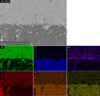 |
Fig. 3 SE-SEM and X-EDS of the 1000 °C Ti-64/H13A ∼0 MPa interface. |
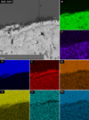 |
Fig. 4 BSE-SEM and XEDS of the 1000 °C Ti-5553/H13A 35 MPa interface. |
 |
Fig. 5 Medium (a) and higher (b) magnification BSE-SEM micrograph of the 1200 °C Ti-64/H13A 850 MPa diffusion couple interface. |
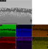 |
Fig. 6 BSE-SEM and XEDS of the 1200 °C Ti-64/ H13A 850 MPa interface. |
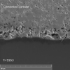 |
Fig. 7 SE-SEM image of 1200 °C Ti-64/H13A 2.5 GPa diffusion couple. |
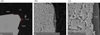 |
Fig. 8 SE-SEM image of the cutting edge from a milling insert used to mill Ti-64. (a) Is a macro low magnification image which shows the rake and flank of the tool and the location of the higher magnification images (b) and (c). |
5 Conclusion
The work presented has provided significant evidence of pore formation within WC-Co tools during the machining of titanium alloys. Void formation is a phenomenon that is observed in both WC-Co inserts used for milling and WC-Co Ti-64/Ti-5553 diffusion couples made at various pressures (0–2.5 GPa) and temperatures (800–1200 °C). Temperature and specifically heating rate likely influence the location and morphology of porosity more than pressure in the analysed diffusion couples. When the heating rate of diffusion couple is slow the conditions for Kirkendall porosity do not occur since reaction layers form, blocking the outward diffusion of Co from the substrate, by removing the metal-metal contact between Ti and Co. Without outward diffusion of Co, and no metal-metal contact the conditions for Kirkendall porosity are not met. The fact that we see voids in both the diffusion couples and machined samples is key. Since porosity occurs in the diffusion couples which haven’t undergone plastic deformation rules out that voids are due to rapid deformation rates. In addition, porosity also occurs in milling, where there is no evidence of η phase, which shows that porosity isn’t due to volumetric reduction when WC transforms to η phase. In milling the metal-metal contact between Ti and Co is observed and thus the conditions for rapid outward diffusion of Co (104 times larger than inward diffusion of Ti), and the conditions for Kirkendall porosity are satisfied. The pores observed within the milling insert have the potential to reduce the integrity of the tool within this region and could be exacerbated by plastic deformation. Since the porosity found in milling inserts was only found to 15 microns below the subsurface it is likely resultant from indicates from diffusional effects, if it were initiated by plastic deformation porosity should be visible within the stress effected zone, which is considerably larger than 15 μm.
These results lay the foundation for future work which could consider testing the theory laid out in this paper. This could be achieved by in some way deliberately forming/creating a diffusion hindering layer on the top of the tool substrate to retard or stop the outward diffusion of Co from the tool material. In a similar way, the tool binder could also be tailored to reduce the Co diffusion rate, thus removing the conditions that satisfy Kirkendall porosity formation. To investigate and prove that Kirkendall porosity occurs in this system it would be elucidating to create a metal-metal diffusion couple containing just titanium and Co.
Nomenclature
Techniques:
AES: Auger electron spectroscopy
BSE-SEM: Back-scattered electron scanning electron microscopy
CALPHAD: CALculation of PHAse Diagrams
EDP: Electron diffraction patterning
EPMA: Electron microprobe analysis
FAST: Field assisted sintering technology
FEM: Finite element method
SAED: Selected area electron diffraction
SE-SEM: Secondary electron scanning electron microscopy
SEM: Scanning electron microscopy
STEM: Scanning transmission electron microscopy
STEM-EDS: Scanning transmission electron microscopy-Energy dispersive X-ray spectroscopy
STEM-EELS: Scanning transmission electron microscopy-electron energy loss spectroscopy
WDS: Wavelength dispersive spectroscopy
X-EDS: Energy dispersive X-ray spectroscopy
XRD: X-Ray diffraction
α:: Hexagonal close-packed Titanium, hcp-Ti
β:: Body-centred cubic Titanium, bcc-Ti
ae:: Radial depth of cut (mm)
ap:: Depth of cut (mm)
Dc:: Cutter diameter (mm)
fz:: Cutting feed (mm/min)
PCBN:: Cubic boron nitride
PCD: Polycrystalline diamond
Ti-64: Ti-6Al-4V
Ti-5553: Ti-5Al-5Mo-5V-3Cr
TiC: Titanium carbide
vc: Cutting speed (m/min)
WC-Co: Tungsten carbide-cobalt
Funding
This work was funded by Sandvik Coromant.
Conflicts of interest
The authors have nothing to disclose.
Data availability statement
This article has no associated data generated and/or analysed.
Author contribution statement
All authors have reviewed, discussed, and agreed to their individual contributions ahead of this time. Contributions will be published before the references section, and they should accurately reflect contributions to the work. The following statements should be used "Conceptualization, All.; Methodology, All.; Software, NA.; Validation, All.; Formal Analysis, All; Investigation, All.; Resources, All; Data Curation, All; Writing − Original Draft Preparation, A.G; Writing − Review & Editing, All; Visualization, All; Supervision, NA; Project Administration, NA; Funding Acquisition, S.N and V.B”.
Supplementary Material
The Supplementary Material is available at https://www.metal.org/10.1051/metal/2025080/olm. Access Supplementary Material
References
- R. Evans, Selection and testing of metalworking fluids, in Metalworking Fluids (MWFs) for Cutting and Grinding, edited by V. P. Astakhov and S. Joksch (Woodhead Publ. Ser. Met. Surf. Eng., 2012), pp. 23–78 [Google Scholar]
- X. Zhao, W. Ke, S. Zhang et al., Potential failure cause analysis of tungsten carbide end mills for titanium alloy machining, Eng. Failure Anal. 66, 321–327 (2016) [Google Scholar]
- P.-J. Arrazola, A. Garay, L.-M. Iriarte et al., Machinability of titanium alloys (Ti6Al4V and Ti555.3), J. Mater. Process. Technol. 209, 2223–2230 (2009) [Google Scholar]
- Z. Wang, M. Rahman, High-speed machining, in Comprehensive Materials Processing, edited by S. Hashmi, G.F. Batalha, C.J. Van Tyne, B. Yilbas (Elsevier, 2014), pp. 221–253 [Google Scholar]
- P.A. Dearnley, A.N. Grearson, Evaluation of principal wear mechanisms of cemented carbides and ceramics used for machining titanium alloy IMI 318, Mater. Sci. Technol. 2, 47–58 (1986) [Google Scholar]
- L. Liao, F. Cai, X. Chang et al., A novel slurry for ultra-smooth chemical mechanical polishing of TC4 titanium alloy, Appl. Surf. Sci. 686, 162167 (2025) [Google Scholar]
- Y. Su, N. He, L. Li et al., An experimental investigation of effects of cooling/lubrication conditions on tool wear in high-speed end milling of Ti-6Al-4V, Wear 261, 760–766 (2006) [Google Scholar]
- A. Graves, A. Salmasi, S. Graham et al., An experimental and theoretical investigation on Ti-5553/WC-Co (6%) chemical interactions during machining and in diffusion couples, Wear 516, 204604 (2023) [Google Scholar]
- R. Lindvall, J.M.B. Bermejo, A. Bjerke et al., On the wear mechanisms of uncoated and coated carbide tools in milling titanium alloys, Int. J. Refractory Metals Hard Mater. 106806 (2024) [Google Scholar]
- W. Min, Z. Youzhen, Diffusion wear in milling titanium alloys, Mater. Sci. Technol. 4, 548–553 (1988) [Google Scholar]
- C. Botermans, Study of Porosity in Uncoated Cemented Carbide Tools During Titanium Alloy Machining, M.S. thesis, Dept. of Mechanical Engineering, Lund University, Lund, Sweden (2023) [Google Scholar]
- P.D. Hartung, B.M. Kramer, B.F. Von Turkovich, Tool wear in titanium machining, CIRP Ann. 31, 75–80 (1982) [Google Scholar]
- S. Norgren, Sandvik Coromant internal report CTMI1314, unpublished, May 13, (2002) [Google Scholar]
- O. Hatt, On the mechanism of tool crater wear in titanium alloy machining, Doctoral dissertation, Dept. of Mechanical Engineering, University of Sheffield, Sheffield, UK (2016) [Google Scholar]
- O. Hatt, P. Crawforth, M. Jackson, On the mechanism of tool crater wear during titanium alloy machining, Wear 374–375, 15–20 (2017) [Google Scholar]
- O. Hatt, Z. Lomas, M. Thomas et al., The effect of titanium alloy chemistry on machining induced tool crater wear characteristics, Wear 408–409, 200–207 (2018) [Google Scholar]
- C. Ramirez, A.I. Ismail, C. Gendarme et al., Understanding the diffusion wear mechanisms of WC-10% Co carbide tools during dry machining of titanium alloys, Wear 390–391, 61–70 (2017) [Google Scholar]
- S. Odelros, B. Kaplan, M. Kritikos et al., Experimental and theoretical study of the microscopic crater wear mechanism in titanium machining, Wear 376–377, 115–124 (2017) [Google Scholar]
- B. Kaplan, S. Odelros, M. Kritikos et al., Study of tool wear and chemical interaction during machining of Ti6Al4V, Int. J. Refract. Met. Hard Mater. 72, 253–256 (2018) [Google Scholar]
- L. von Fieandt, R. M’Saoubi, M. Schwind et al., Chemical interactions between cemented carbide and difficult-to-machine materials by diffusion couple method and simulations, J. Phase Equilibria Diffus. 39, 369–376 (2018) [Google Scholar]
- M. Latteman, E. Coronel, J. Garcia, et al., Interaction between cemented carbide and Ti6Al4V alloy in cryogenic machining, in Proceedings of the 19th Plansee Seminar, Reutte, Austria 29, (2017) [Google Scholar]
- S. Saketi, S. Odelros, J. Östby et al., Experimental study of wear mechanisms of cemented carbide in the turning of Ti6Al4V, Materials 12, 2822 (2019) [Google Scholar]
- A. Graves, S. Norgren, W. Wan et al., On the mechanism of crater wear in a high strength metastable β titanium alloy, Wear 484, 203998 (2021) [Google Scholar]
- R. Lindvall, F. Lenrick, R. M’Saoubi et al., Performance and wear mechanisms of uncoated cemented carbide cutting tools in Ti6Al4V machining, Wear 477, 203824 (2021) [Google Scholar]
- P. Olander, J. Heinrichs, On wear of WC-Co cutting inserts in turning of Ti6Al4V-a study of wear surfaces, Tribology-Mater. Surfac. Interfaces 15, 181–192 (2021) [Google Scholar]
- R. Bejjani, C. Salame, M. Olsson, An experimental and finite element approach for a better understanding of ti-6al-4v behavior when machining under cryogenic environment, Materials 14, 2796, (2021) [Google Scholar]
- A. Henjered, M. Hellsing, H.-O. Andrén, H. Nordén, Quantitative microanalysis of carbide/carbide interfaces in WC–Co-base cemented carbides, Mater. Sci. Technol. 2, 847–855 (1986) [Google Scholar]
- R.S. Barnes, D.J. Mazey, The effect of pressure upon void formation in diffusion couples, Acta metallurgica 6, 1–7 (1958) [Google Scholar]
Cite this article as: Alexander Graves, Rebecka Lindvall, Cornelis Botermans, Martin Jackson, Volodymyr Bushlya, Susanne Norgren, Kirkendall pore formation within WC-Co tool inserts during the machining of titanium alloys, Metall. Res. Technol. 122, 608 (2025), https://doi.org/10.1051/metal/2025080
All Tables
All Figures
|
Fig. 1 Binary Co-W phase diagram calculated using the Thermocalc software and the binary database (TCBIN). The dashed arrow indicates the W supersaturation at a 1000 °C in the Cobalt to precipitate the Co3W phase and where fcc* denotes the magnetic fcc [13]. |
| In the text | |
|
Fig. 2 Temperature during diffusion couple manufacture for Ti-5553/H13A and Ti-64/H13A ∼0 MPa, Ti-5553/H13A 35 MPa, Ti 5553/H13A and Ti-64/H13A 450 MPa and Ti-64/H13A 2.5 GPa. |
| In the text | |
|
Fig. 3 SE-SEM and X-EDS of the 1000 °C Ti-64/H13A ∼0 MPa interface. |
| In the text | |
|
Fig. 4 BSE-SEM and XEDS of the 1000 °C Ti-5553/H13A 35 MPa interface. |
| In the text | |
|
Fig. 5 Medium (a) and higher (b) magnification BSE-SEM micrograph of the 1200 °C Ti-64/H13A 850 MPa diffusion couple interface. |
| In the text | |
|
Fig. 6 BSE-SEM and XEDS of the 1200 °C Ti-64/ H13A 850 MPa interface. |
| In the text | |
|
Fig. 7 SE-SEM image of 1200 °C Ti-64/H13A 2.5 GPa diffusion couple. |
| In the text | |
|
Fig. 8 SE-SEM image of the cutting edge from a milling insert used to mill Ti-64. (a) Is a macro low magnification image which shows the rake and flank of the tool and the location of the higher magnification images (b) and (c). |
| In the text | |
Current usage metrics show cumulative count of Article Views (full-text article views including HTML views, PDF and ePub downloads, according to the available data) and Abstracts Views on Vision4Press platform.
Data correspond to usage on the plateform after 2015. The current usage metrics is available 48-96 hours after online publication and is updated daily on week days.
Initial download of the metrics may take a while.